
Fundus camera bracket and fundus camera with same

A bracket and camera technology, which is applied in the fields of ophthalmoscope, eye testing equipment, medical science, etc., can solve the problems that the function richness of the fundus camera bracket needs to be improved, the operation of medical personnel is incoherent, and the operation fails. Mass production processing, reducing operation failure rate, increasing functional effect

Active Publication Date: 2020-11-06
吉林至真明熠医疗器械有限公司
View PDF15 Cites 1 Cited by
  • Summary
  • Abstract
  • Description
  • Claims
  • Application Information

AI Technical Summary

Problems solved by technology

[0003] At present, the fundus camera bracket can only support the fundus camera, and when the fundus camera is needed for shooting, the camera still needs to be operated, resulting in incoherent or even failed operations by medical personnel. The richness of functions of the fundus camera bracket needs to be improved

Method used


Image

  • Fundus camera bracket and fundus camera with same
  • Fundus camera bracket and fundus camera with same
  • Fundus camera bracket and fundus camera with same

Examples


Embodiment Construction

[0022] Various exemplary embodiments, features, and aspects of the present application will be described in detail below with reference to the accompanying drawings. The same reference numbers in the figures indicate functionally identical or similar elements. While various aspects of the embodiments are shown in drawings, the drawings are not necessarily drawn to scale unless specifically indicated.

[0023] Wherein, it should be understood that the terms "center", "longitudinal", "transverse", "length", "width", "upper", "lower", "front", "rear", "left", "right" ", "Vertical", "Horizontal", "Top", "Bottom", "Inner", "Outer", "Clockwise", "Counterclockwise", "Axial", "Radial", "Circumferential ” and other indicated orientations or positional relationships are based on the orientations or positional relationships shown in the drawings, and are only for the convenience of describing the present invention or simplifying the description, rather than indicating or implying that t...


PUM


Abstract

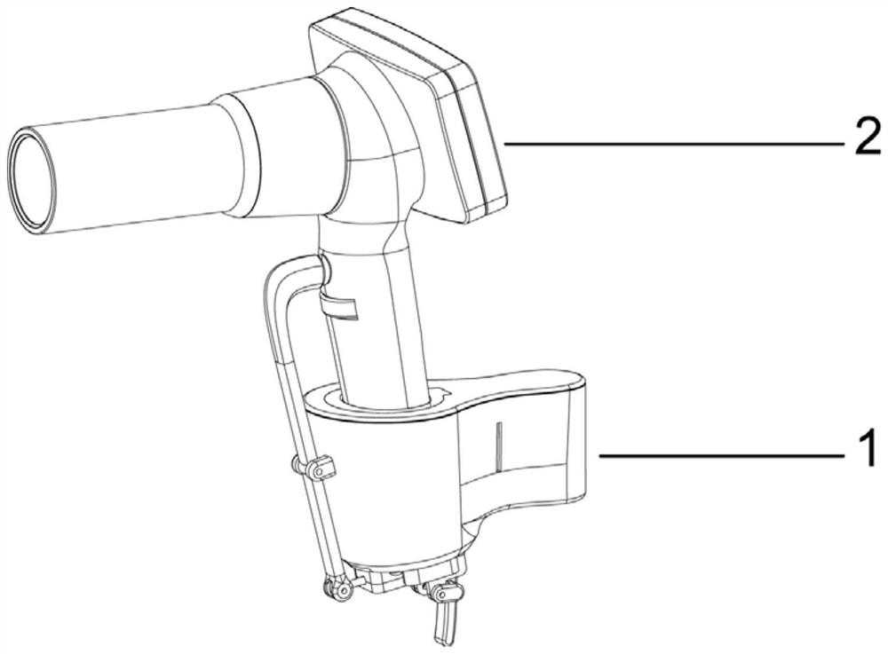
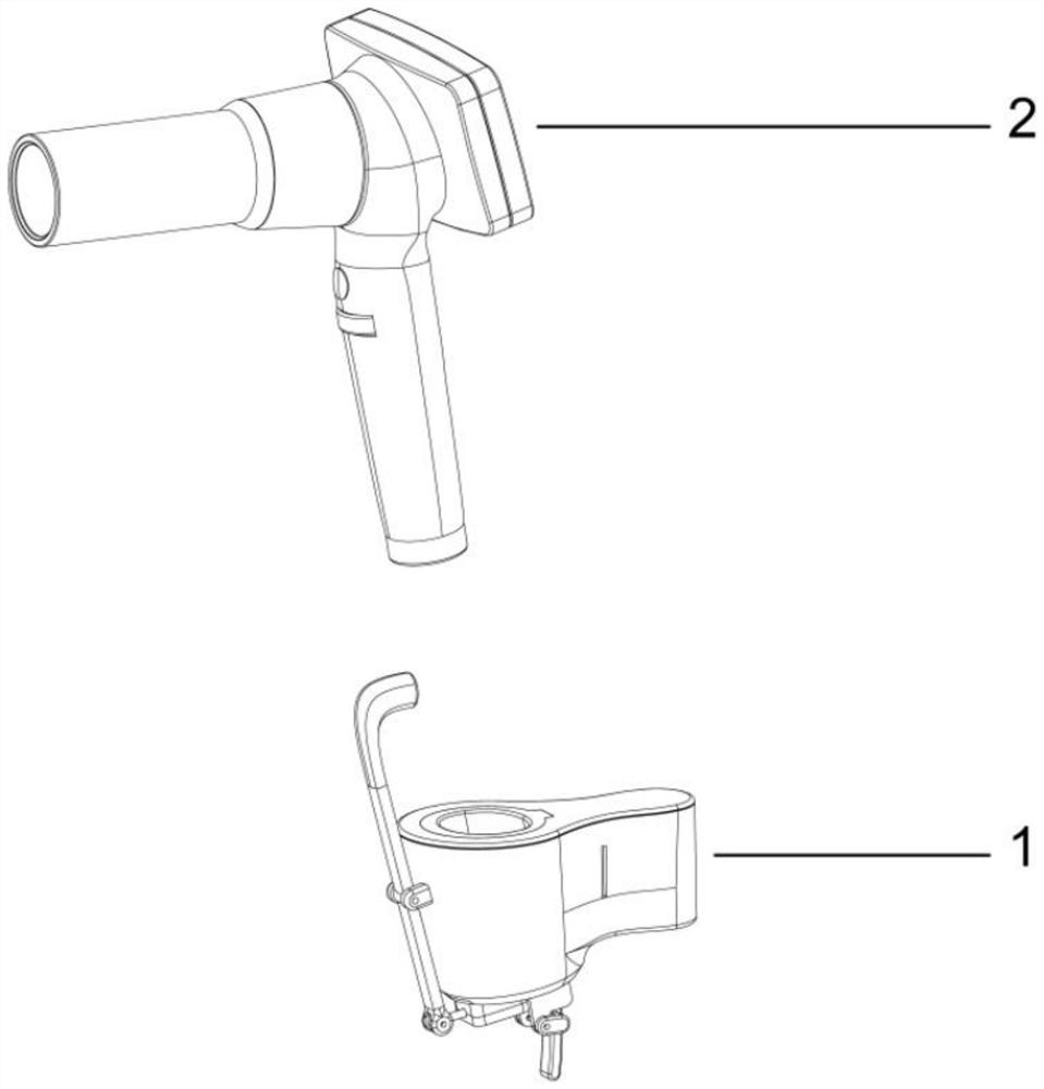
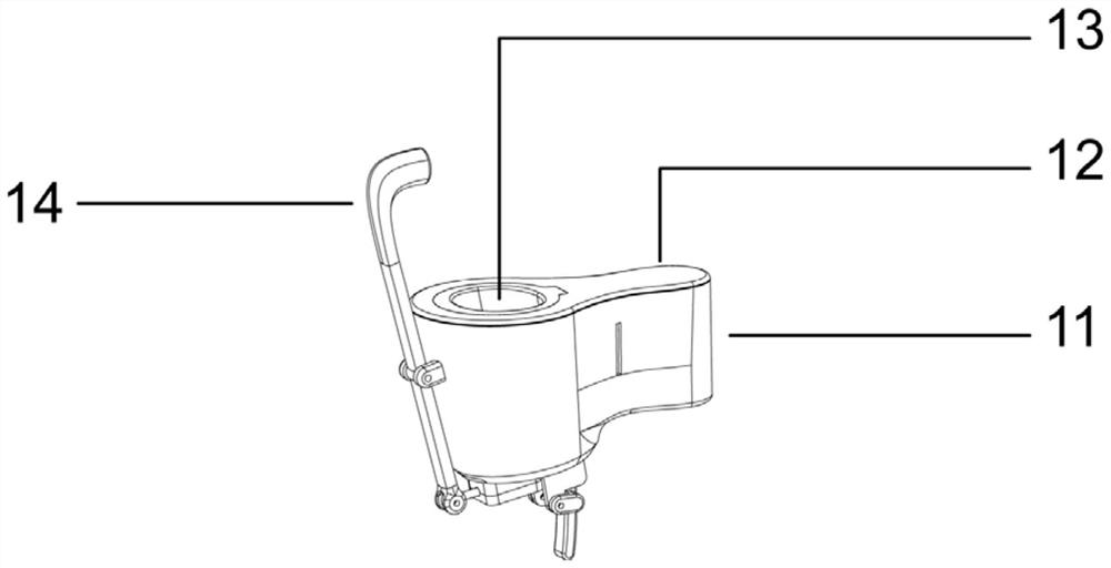
The application relates to a fundus camera bracket which comprises a bracket, a trigger connection rod and a trigger power assembly. A groove is formed at the upper end of the bracket, and the grooveis suitable for being matched with a fundus camera; the trigger power assembly is arranged at the lower end of the bracket; a first end of the trigger connection rod is suitable for being connected with a shooting button of the fundus camera, while a second end is connected with the trigger power assembly; and when the trigger power assembly moves by an external force, the trigger power assembly presses or is separated from the shooting button of the fundus camera by the trigger connection rod. According to the fundus camera bracket disclosed by the application, when the bracket can be guaranteed to stably support and fix the fundus camera, a shooting function of the fundus camera is operated by pressing a trigger on the bracket, thereby improving functionality of the bracket and facilitating operation of those skilled in the art; and the fundus camera bracket can be held with double hands in the whole process, so that the operation of shooting by the fundus camera is more coherent andan operation failure rate is reduced. The fundus camera bracket adopts pure mechanical structure composition and does not need to be connected with a circuit or carry out Bluetooth adapting, a faultrate of equipment is greatly reduced, and the fundus camera bracket is low in cost and easy for mass production machining.

Description

technical field [0001] The present application relates to the field of camera bracket systems, in particular to a fundus camera bracket and a fundus camera with the same. Background technique [0002] Handheld fundus cameras belong to the field of medical imaging, and are mostly used by medical personnel to detect fundus diseases of patients or assist in judging the conditions of other organs. Because the blood vessels of the fundus are the only blood vessels that can be directly observed through the body surface, medical personnel can diagnose various diseases through the fundus camera, and early detection is more conducive to clinical treatment. Therefore, the fundus camera is generally used for clinical screening of fundus diseases. [0003] At present, the fundus camera bracket can only support the fundus camera, but when the fundus camera is needed for shooting, the camera still needs to be operated, resulting in incoherent or even failed operations by medical personnel...

Claims


Application Information

Patent Timeline
IPC IPC(8): A61B50/22A61B3/14A61B3/12
CPCA61B3/12A61B3/14A61B50/22
Inventor 张冬冬刘鹏呼伦夫赵成成于志强
Owner 吉林至真明熠医疗器械有限公司
Learn More