a brake drum

A technology for brake drums and brake parts, applied to brake drums, slack adjusters, etc., can solve the problems of large rotating centrifugal force, affecting the service life of bearings, increasing bearing burden, etc., to reduce rotating centrifugal force and external throwing force, and improve processing The effect of high efficiency and reduced burden

Active Publication Date: 2018-04-06
SHANDONG HAOXIN MACHINERY
View PDF14 Cites 1 Cited by
  • Summary
  • Abstract
  • Description
  • Claims
  • Application Information

AI Technical Summary

Problems solved by technology

[0009] The purpose of the embodiment of the present invention is to provide a brake drum to solve the problem that the existing brake drum will generate a large rotational centrifugal force during operation, increase the burden on the bearing, and affect the service life of the bearing

Method used


Image

  • a brake drum
  • a brake drum
  • a brake drum

Examples


Embodiment 1

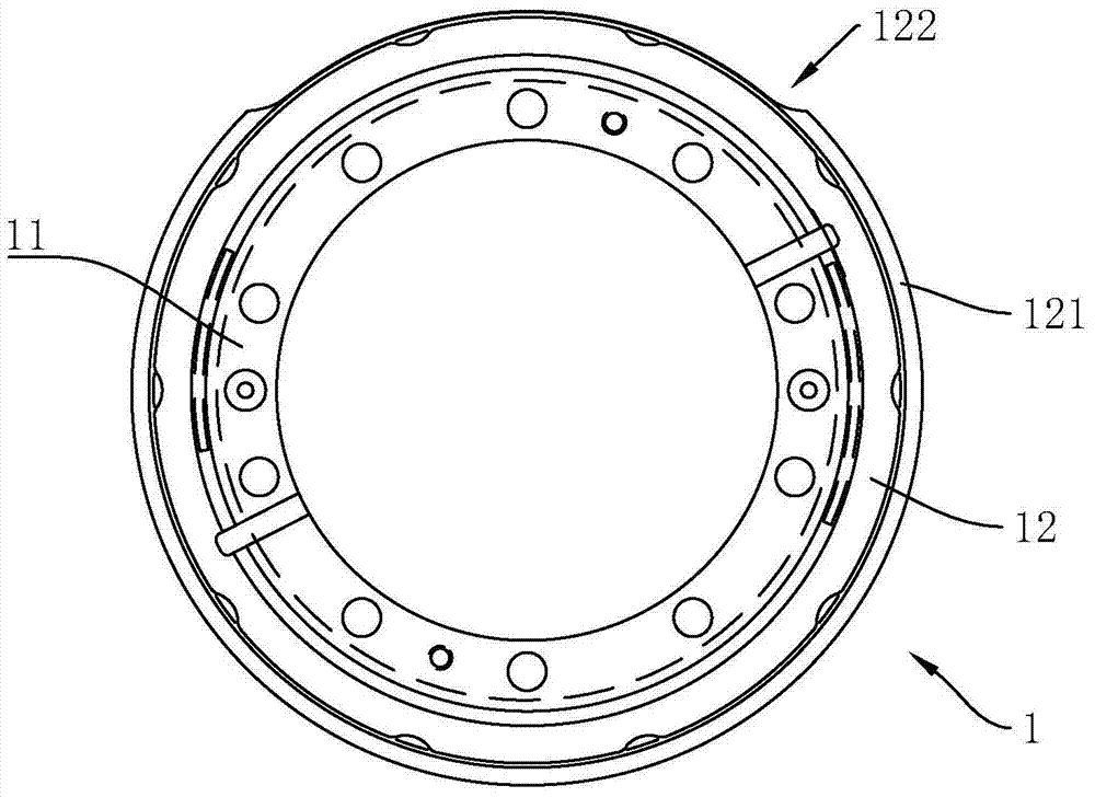
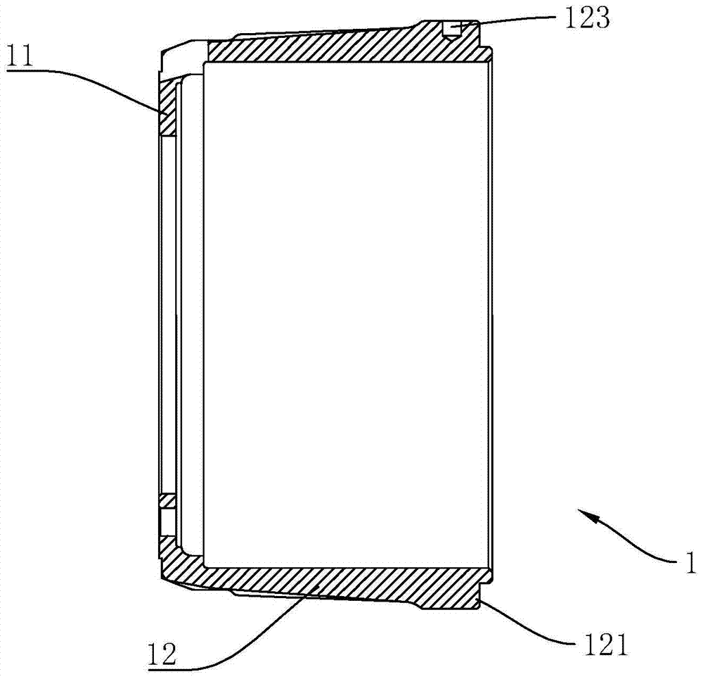
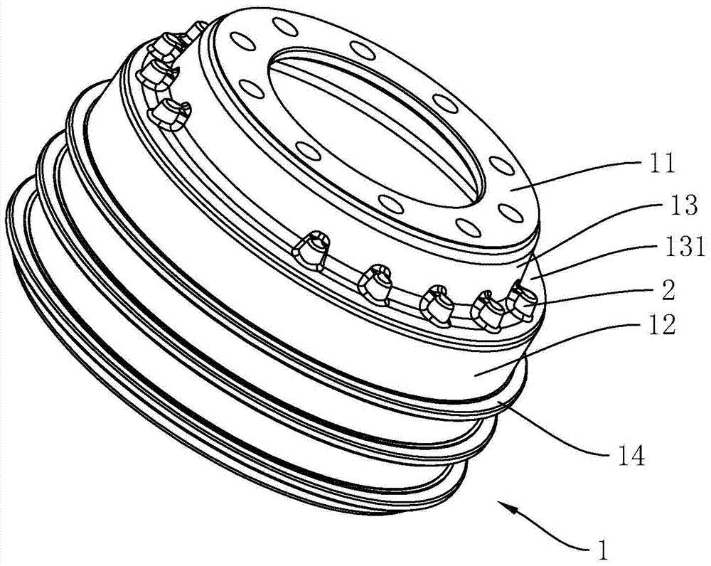
[0045] Such as Figure 3 to Figure 6 Commonly shown, a brake drum includes a casted brake drum body 1, the brake drum body 1 includes a hub connecting portion 11 for connecting with a wheel hub and a brake pad for cooperating with a brake shoe. part 12, a transition connection part 13 is provided between the hub connection part 11 and the brake part 12, a step part 131 is provided on the transition part 13, and a step part 131 is provided for adjusting the balance of the brake drum body 1. the balance department.

[0046] The balance portion includes a plurality of bosses 2 arranged on the transition connection portion 13 , and the bosses 2 extend toward the hub connection portion 11 . The formation process of the final finished brake drum is as follows: first, the brake drum body 1 is cast and formed, and at the same time, the bosses 2 are formed in an annular array on the transition connecting portion 13 (such as Figure 4 shown), and then according to the calculation of t...

Embodiment 2

[0050] Such as Figure 7 and Figure 8 Commonly shown, the specific structure of this embodiment is the same as that of Embodiment 1, the difference being:

[0051]The hoop 14 is a hoop 141 tightly fitted on the outer periphery of the brake part 12. A plurality of axially arranged annular ribs 143 protrude from the outer circumference of the hoop 141. The hoop between two adjacent annular ribs 143 A plurality of cooling grooves 142 are arranged circularly on the sleeve 141; the clamp 14 can be an aluminum clamp or a steel clamp. The hoop 14 with this structure has good covering ability on the brake part 12 and high working strength, and can effectively prevent fragments from splashing out after the brake drum body 1 is broken, thereby improving safety.

Embodiment 3

[0053] Such as Figure 9 and Figure 10 Commonly shown, the specific structure of this embodiment is the same as that of Embodiment 1, the difference being:

[0054] The balance part includes at least one counterweight body 3 fixed on the transitional connection part 13 (specifically: the stepped part 131) through the fastener 22, the counterweight body 3 is provided with a long hole 31, and the counterweight body 3 is a sheet structure and the weight body 3 is of a bent structure (that is, the bent portion 32 in the figure), the above can be regarded as a single embodiment.

[0055] As a preference, there are several protrusions 6 in an annular array on the transition connection part 13 (specifically: the stepped part 131), and the weight body 3 is installed on at least one protrusion 6 through a fastener 22. The specific structure is: the protrusion Block 6 is provided with connection hole 21, and this connection hole 21 is threaded hole, and this fastener 22 is the bolt o...


PUM


Abstract

The invention discloses a brake drum. The brake drum comprises a brake drum body. The brake drum body comprises a hub connecting part and a brake part. A transition connecting part is arranged between the hub connecting part and the brake part and provided with a balance part used for adjusting the balance amount of the brake drum body. Compared with the prior art, the balance part achieving the adjustment on the balance amount is far away from the brake part and is close to the hub connecting part, meanwhile, the balance amount of the brake drum body in the axial direction is achieved, and the rotation centrifugal force and external throwing force are greatly reduced; and accordingly, the burden of a bearing is greatly reduced, and the service life of the bearing is prolonged.

Description

technical field [0001] The invention belongs to the technical field of automobile brake systems, and in particular relates to a brake drum. Background technique [0002] At present, the existing brake drum body 1 includes the hub connecting portion 11 and the braking portion 12. In order to ensure the dynamic balance, the following two methods are generally adopted: [0003] The first (see figure 1 ): An annular flange 121 is cast and formed on the brake part 12. The annular flange 121 is located at the end away from the hub connection part 11. In order to ensure the balance, milling is performed on the annular flange 121 in the area that affects the balance. Machined with milled slots 122; [0004] The second (see figure 2 ):and figure 1 The first structure shown is similar, the difference being that, in order to ensure the balance, a bore 123 is drilled on the annular flange 121 . [0005] Adopt the brake drum of above-mentioned two kinds of structures, there is foll...

Claims


Application Information

Patent Timeline
Patent Type & Authority Patents(China)
IPC IPC(8): F16D65/10F16D65/78
Inventor 吕继贤蒲光明
Owner SHANDONG HAOXIN MACHINERY
Why Eureka
Try Eureka