
Phase-change switch

A technology of commutation switch and power supply, which is applied in the direction of electric switch, multi-phase network asymmetry reduction, multi-phase network elimination/reduction of asymmetry, etc., which can solve problems such as current imbalance, fire, motor heating, etc., to avoid motor reverse effect

Active Publication Date: 2021-10-22
TIANJIN SVRUI INTELLIGENT ELECTRICAL CO LTD
View PDF7 Cites 2 Cited by
  • Summary
  • Abstract
  • Description
  • Claims
  • Application Information

AI Technical Summary

Problems solved by technology

[0002] In my country's current low-voltage power distribution three-phase four-wire power grid, single-phase loads account for the majority. These single-phase loads have large irregularities due to actual application conditions and time distribution, resulting in serious three-phase current imbalances in the power grid. Problems, it is easy to cause single-phase current or the center line is too large, increase the copper loss and iron loss of the line and transformer, cause the line to be overloaded or short-circuited, and even cause the cable to catch fire at high temperature and cause a fire accident, which is not conducive to the safety of power supply
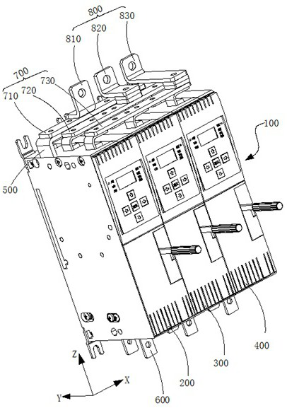
[0003] As a typical application to solve the three-phase unbalance problem, the phase-change switch has been used more and more. The existing phase-change switches with three-phase incoming lines and one-phase outgoing lines mostly use three electromagnets to drive three sets of moving and static contacts. ,like figure 1 In the patent 201610916682.X shown, the switch disclosed in this patent uses three electromagnets and three sets of dynamic and static contacts to achieve three-way incoming lines and one-way outgoing line commutation; figure 2 The Chinese patent 201821456019.7 shown in the figure uses an electromagnet to drive a rotating plug-in contact to achieve phase change of three incoming lines and one outgoing line. The technologies of the above two patents both switch the full current of the phase line when performing the phase commutation action. To another phase line, this switching method often causes the current of the other phase line to be too high, resulting in a new current imbalance, which is not conducive to the balanced switching of the three-phase current of the system; in the case of three-phase loads, such as three-phase For the motor, the full current switching of the above two patents will cause the phase sequence of the motor to change, which will cause the motor to reverse or stop, causing the motor to heat up and bring mechanical and electrical shocks at the same time, causing the motor to break and burn. Bring equipment damage and production economic loss

Method used


Image

  • Phase-change switch
  • Phase-change switch
  • Phase-change switch

Examples


Embodiment Construction

[0034] Features and exemplary embodiments of various aspects of the invention will be described in detail below. In the following detailed description, numerous specific details are set forth in order to provide a thorough understanding of the present invention. It will be apparent, however, to one skilled in the art that the present invention may be practiced without some of these specific details. The following description of the embodiments is only to provide a better understanding of the present invention by showing examples of the present invention. The present invention is by no means limited to any specific configuration set forth below, but covers any modification, substitution and improvement of elements, components without departing from the spirit of the invention. In the drawings and the following description, well-known structures and techniques have not been shown in order to avoid unnecessarily obscuring the present invention.

[0035] For the convenience of d...


PUM


Abstract

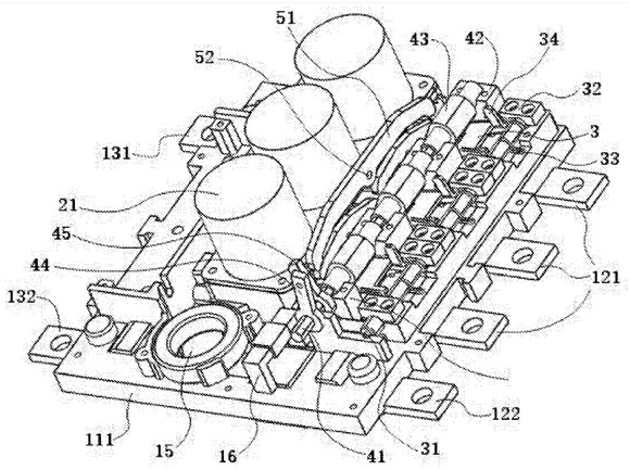
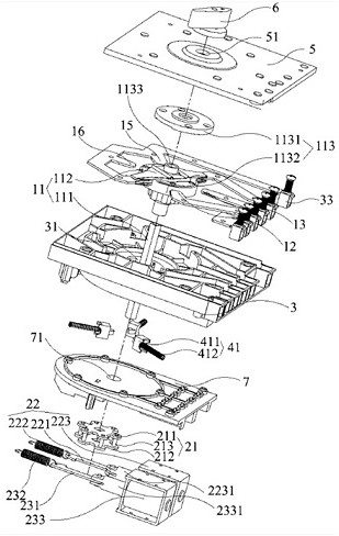
The invention discloses a phase-change switch, and the switch comprises an insulating shell, power supply wire inlet ends, power supply wire outlet ends, at least one moving contact and at least two static contacts; the power supply wire inlet ends comprise a first power supply wire inlet end and a second power supply wire inlet end, and the power supply wire outlet ends comprise a first power supply wire outlet end and a second power supply wire outlet end. The second power supply wire inlet end is electrically connected with the second power supply wire outlet end through the static contact and the moving contact, the first power supply wire inlet end is directly and electrically connected with the first power supply wire outlet end, and the first power supply wire outlet end and the second power supply wire outlet end are insulated from each other. According to the invention, one path of power supply wire outlet end is directly communicated with one path of power supply wire inlet end, so only part of current can be converted during commutation, and inter-phase current balance can be achieved more favorably.

Description

technical field [0001] The invention relates to the field of low-voltage electrical appliances, in particular to a phase change switch applied to unbalanced three-phase loads. Background technique [0002] In my country's current low-voltage power distribution three-phase four-wire power grid, single-phase loads account for the majority. These single-phase loads have large irregularities due to actual application conditions and time distribution, resulting in serious three-phase current imbalances in the power grid. Problems, it is easy to cause single-phase current or excessive central line, increase the copper loss and iron loss of the line and transformer, lead to line overload or short circuit, and even lead to high temperature and fire of the cable, causing fire accidents, which is not conducive to power supply safety. [0003] As a typical application to solve the three-phase unbalance problem, the phase-change switch has been used more and more. The existing phase-chan...

Claims


Application Information

Patent Timeline
Patent Type & Authority Applications(China)
IPC IPC(8): H01H9/00H02J3/26
CPCH01H9/00H02J3/26Y02E40/50
Inventor 南寅沈迪王文涛任庆庆董郁朱金保
Owner TIANJIN SVRUI INTELLIGENT ELECTRICAL CO LTD
Learn More