Vertical centrifugal oil separator

An oil separator, centrifugal technology, used in refrigeration components, refrigerators, lighting and heating equipment, etc., can solve the problem of affecting the separation effect of the filter screen on small particle oil droplets, the centrifugal oil separator is not very good, The separation effect needs to be improved to achieve the effect of increasing the aggregation, increasing the separation effect, and improving the separation effect

Inactive Publication Date: 2016-01-20
XINCHANG HONGYU REFRIGERATION CO LTD
View PDF6 Cites 6 Cited by
  • Summary
  • Abstract
  • Description
  • Claims
  • Application Information

AI Technical Summary

Problems solved by technology

[0002] The function of the oil separator is to separate the lubricating oil in the high-pressure steam discharged from the refrigeration compressor to ensure the safe and efficient operation of the device. According to the oil separation principle of reducing the airflow speed and changing the airflow direction, the oil particles in the high-pressure steam It can be separated under the action of gravity. There are four types of oil separators commonly used: washing type, centrifugal type, packing type and filter type. The spiral guide vane of the existing centrifugal oil separator generally does not have a spiral collector Therefore, the separation effect of the existing centrifugal oil separator is not very good; the filter screen of the existing centrifugal oil separator for separating small oil droplets is generally installed in a horizontal state, so the small particles separated on the filter Oil droplets are not easy to slide off the filter screen, which affects the separation effect of the filter screen on small oil droplets; the spiral guide vane of the existing centrifugal oil separator is generally fixed, so the separation of the existing centrifugal oil separator The effect needs to be improved

Method used


Image

  • Vertical centrifugal oil separator
  • Vertical centrifugal oil separator

Examples


Embodiment Construction

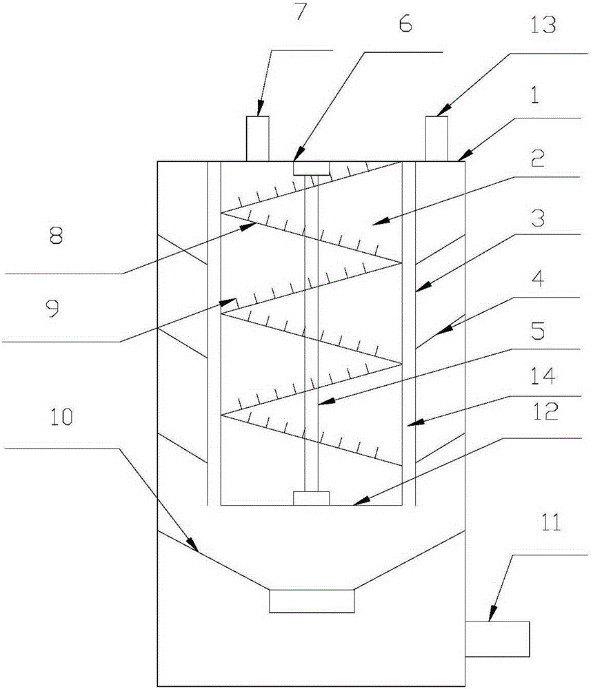
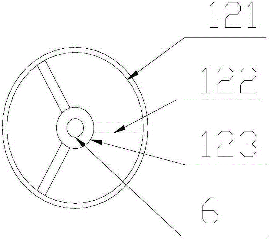
[0015] refer to figure 1 and figure 2 , a vertical centrifugal oil separator of the present invention, comprising a cylinder body 1, a separation cylinder 2, an isolation cylinder 3, a filter screen 4, a rotating shaft 5, a rotating shaft sleeve 6, an air inlet 7, a spiral guide vane 8, an oil collecting Metal wire 9, oil collecting plate 10, automatic oil return valve 11, fixed bracket 12, air outlet 13 and oil discharge groove 14, described separating cylinder 2 and isolating cylinder 3 are directly installed on the upper surface inside cylinder body 1, described The filter screen 4 is installed between the isolation cylinder 3 and the cylinder body 1, the rotating shaft 5 is installed between the cylinder body 1 and the fixed bracket 12 through the rotating shaft sleeve 6, and the cylinder body 1 is provided with an air inlet 7 and an air outlet 13 and automatic oil return valve 11, the spiral guide vane 8 is installed on the rotating shaft 5, the oil collecting metal wir...


PUM


Abstract

The invention discloses a vertical centrifugal oil separator. The vertical centrifugal oil separator comprises a barrel, a separating barrel, an insulating barrel, a filter screen, a rotary shaft, rotary shaft sleeves, an air inlet, spiral guiding vanes, oil collecting metal wires, oil collecting plates, an automatic oil returning valve, a fixing support, an air outlet and an oil discharging groove. According to the vertical centrifugal oil separator, the spiral oil collecting metal wires are added on existing spiral guiding vanes of a centrifugal oil separator, and the spiral guiding vanes of the centrifugal oil separator are changed to be in a rotatable structure mode, so that the separating effect of the existing centrifugal oil separator is greatly improved; a separating filer screen of the existing centrifugal oil separator is changed to be in the shape of a funnel, so that the aggregating property of oil drops on the filter screen is improved and the oil drops on the filter screen can flow down quickly, and thus the separating effect of the filter screen on the small-sized oil drops is improved.

Description

【Technical field】 [0001] The invention relates to the technical field of structural components of refrigeration equipment, in particular to the technical field of a vertical centrifugal oil separator. 【Background technique】 [0002] The function of the oil separator is to separate the lubricating oil in the high-pressure steam discharged from the refrigeration compressor to ensure the safe and efficient operation of the device. According to the oil separation principle of reducing the airflow speed and changing the airflow direction, the oil particles in the high-pressure steam It can be separated under the action of gravity. There are four types of oil separators commonly used: washing type, centrifugal type, packing type and filter type. The spiral guide vane of the existing centrifugal oil separator generally does not have a spiral collector Therefore, the separation effect of the existing centrifugal oil separator is not very good; the filter screen of the existing centr...

Claims


Application Information

Patent Timeline
Patent Type & Authority Applications(China)
IPC IPC(8): F25B43/02
CPCF25B43/02
Inventor 石松
Owner XINCHANG HONGYU REFRIGERATION CO LTD
Why Eureka
Try Eureka