Electric connector

A technology of electrical connectors and docking parts, applied in the direction of connections, circuits, and parts of connection devices, etc., can solve problems such as inability to reduce signal crosstalk, achieve the effect of improving high-frequency transmission capabilities and reducing signal crosstalk

Inactive Publication Date: 2016-01-20
LUXSHARE ELECTRONICS TECH (KUNSHAN) LTD
View PDF10 Cites 14 Cited by
  • Summary
  • Abstract
  • Description
  • Claims
  • Application Information

AI Technical Summary

Problems solved by technology

[0002] For the prior art related to this case, you can refer to an electrical connector disclosed in Chinese Invention Patent Publication No. CN104577460A, which includes an insulating body, a two-terminal module and a metal shell. The front protruding plate-shaped butt joint part, the butt joint part includes opposite upper and lower surfaces and a front end surface and two side surfaces between the upper and lower surfaces, each terminal module includes an insulating block and i

Method used


Image

  • Electric connector
  • Electric connector
  • Electric connector

Examples


Embodiment Construction

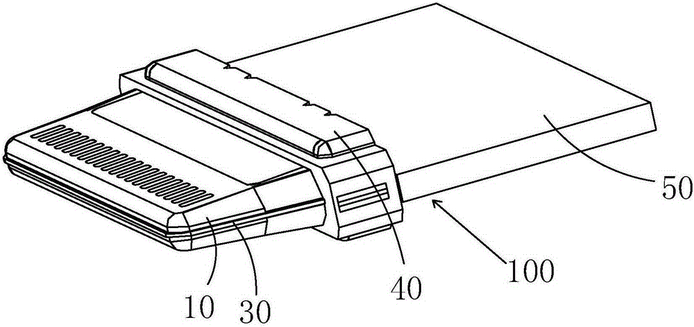
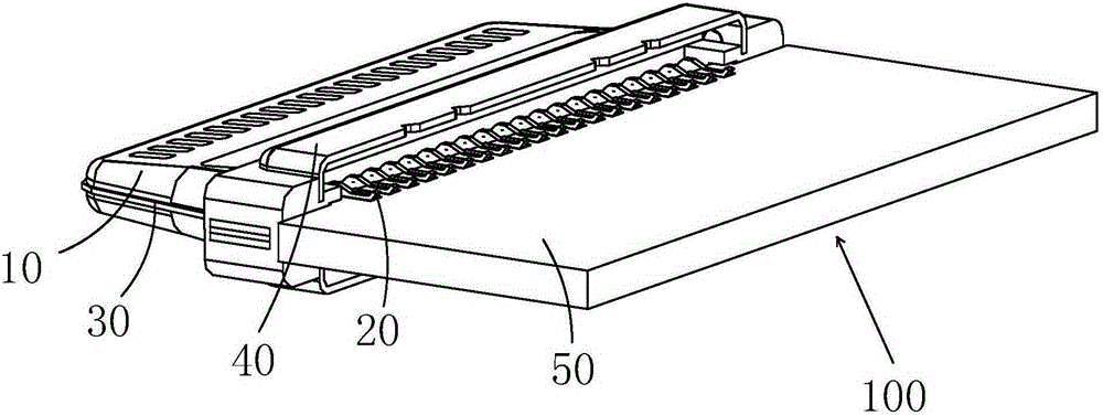
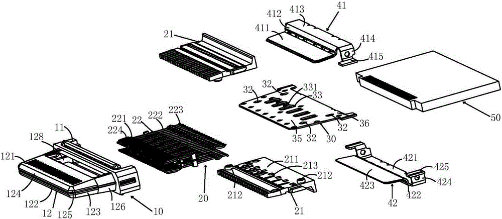
[0020] see Figure 1 to Figure 4 As shown, the electrical connector 100 of the present invention is a plug connector, which is used to be inserted into a mating connector (not shown), which includes an insulating body 10, two terminal modules 20, a metal shielding sheet 30, a The metal shell 40 and a circuit board 50 .

[0021] The insulating housing 10 includes a main body 11 and a plate-shaped butt joint 12 protruding forward from the middle of the main body 11 . The thickness and width of the main body 11 are larger than the butt joint 12 . The docking portion 12 supports forward and reverse insertion of the electrical connector 100 , and the docking portion 12 is symmetrical up and down, left and right, and its thickness and width gradually increase from front to back. The butt joint 12 has opposite upper and lower surfaces 121, 122 and a front end surface 123 between the upper and lower surfaces 121, 122 and opposite side surfaces 124, the upper and lower surfaces 121, 1...


PUM


Abstract

The invention relates to an electric connector comprising an insulation body, two terminal module groups and a metal housing. The insulation body comprises a main body part and a plate-shaped abutted-connection part extending forward from the main body part. The abutted-connection part comprises an upper surface and a lower surface which are opposite and a front end surface and two side surfaces positioned between the upper surface and the lower surface. Each terminal module group comprises an insulation block and a row of conductive terminals fixed on the insulation block. Each conductive terminal comprises a grounding terminal and several differential signal terminals. Each conductive terminal comprises contact parts arranged on the upper surface and the lower surface. The metal housing circles around the outer sides of the terminal module groups. The electric connector is also provided with a metal shielding sheet positioned between the upper surface and the lower surface of the abutted-connection part. The shielding sheet is provided with at least one through hole and an elastic arm extending upwards or downwards in a projection mode from the inner edge of each through hole. Each insulation block is provided with at least one groove used for accommodating the elastic arm. The contacts parts of the grounding terminal are exposed outside of the groove to make contact with the elastic arm. The electric connector of the invention can reduce signal crosstalk.

Description

technical field [0001] The invention relates to an electrical connector, in particular to an electrical connector with a metal shielding sheet. Background technique [0002] For the prior art related to this case, you can refer to an electrical connector disclosed in Chinese Invention Patent Publication No. CN104577460A, which includes an insulating body, a two-terminal module and a metal shell. The front protruding plate-shaped butt joint part, the butt joint part includes opposite upper and lower surfaces and a front end surface and two side surfaces between the upper and lower surfaces, each terminal module includes an insulating block and is fixed on the insulating block A row of conductive terminals on the block, the conductive terminals have contact parts arranged on the upper and lower surfaces, the metal shell surrounds the outside of the terminal module, and the electrical connector is also provided on the docking part, A metal shield between the lower surfaces, ho...

Claims


Application Information

Patent Timeline
IPC IPC(8): H01R13/6596H01R13/648
Inventor 李长茂孙宏伟柯作锦
Owner LUXSHARE ELECTRONICS TECH (KUNSHAN) LTD
Why Eureka
Try Eureka