
Film body, reverse injection molding method for film body, and reverse injection molding tool for film body

An injection molding, film technology, applied in the field of reverse injection molding tools, reverse injection molding, can solve problems such as expensive

Active Publication Date: 2017-10-10
POLYIC GMBH & CO KG
View PDF4 Cites 0 Cited by
  • Summary
  • Abstract
  • Description
  • Claims
  • Application Information

AI Technical Summary

Problems solved by technology

However, this is expensive to implement

Method used


Image

  • Film body, reverse injection molding method for film body, and reverse injection molding tool for film body
  • Film body, reverse injection molding method for film body, and reverse injection molding tool for film body
  • Film body, reverse injection molding method for film body, and reverse injection molding tool for film body

Examples


Embodiment Construction

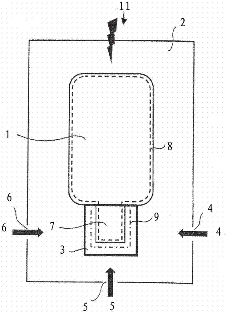
[0046] figure 1 The layer electrode 1 and the sacrificial film 3 inserted into the reverse injection molding tool 2 are shown. The layer electrode 1 with the tail 7 is held by a vacuum line 8 formed in the reverse injection molding tool 2 , while the sacrificial film 3 is held by a second vacuum line 9 different therefrom. This is necessary because in this embodiment example there is no coherent film body comprising both the layer electrode 1 and the sacrificial film 3 . Instead, layer electrode 1 as a first film and sacrificial layer 3 as a second film are present independently therefrom and only loosely arranged on top of each other without being connected to one another.

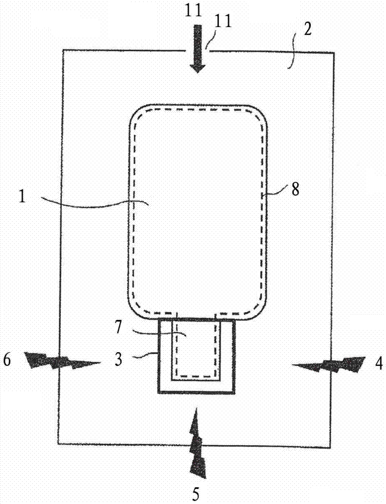
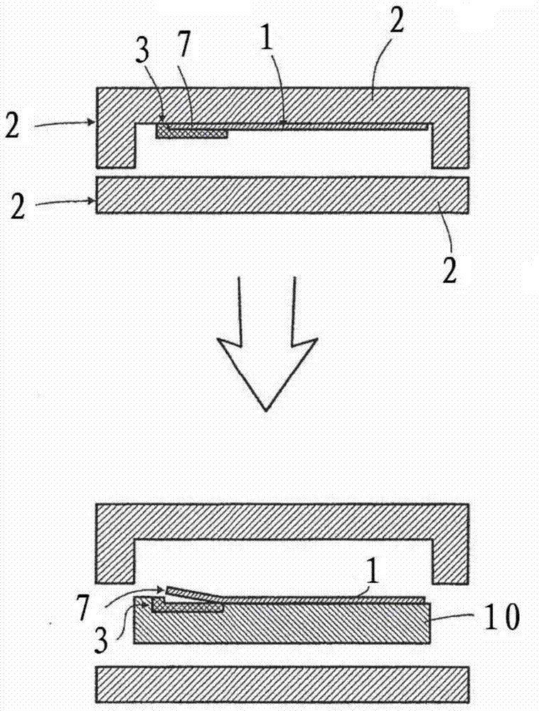
[0047] For reverse injection molding body 10( Figure 2b ) of the formation of reverse injection molding material injection according to the figure 1 The embodiment shown in is implemented by means of openings 4 , 5 or 6 . The direction from which back injection molding material (not shown) arrives in...


PUM

PropertyMeasurementUnit
thicknessaaaaaaaaaa
thicknessaaaaaaaaaa

Abstract

The present invention relates to a foil body, a method for back injection molding a foil body, and a back injection molding tool. The invention particularly relates to a method for back injection moulding layer electrodes (1) for the production of touch sensitive sensors such as touch screens. In this method, the part of the layer electrode (1) which is still free to move after back injection molding is covered by a sacrificial foil (3) before and during the back injection molding process.

Description

technical field [0001] The present application relates to a film body, a method for reverse injection molding of a film body, and a reverse injection molding tool for the film body. In particular, the invention relates to a method of reverse injection molding of layer electrodes for touch screens. Background technique [0002] Layer electrodes form the core of the touch screen. In these layer electrodes the individual sensor arrays are contacted and the supply lines are joined together at the edge of the layer electrodes, bundled and plugged into eg ZIF connectors as so called "tails" for electrical connection to the touch module or controller. [0003] The tail is thus the component of the film that provides the layer electrodes. This film portion, described as the "tail", differs from the larger portion of the layer electrode in that it has a different wire coverage than the layer electrode, including the bundled supply wires to the sensor electrode array connections of ...

Claims


Application Information

Patent Timeline
Patent Type & Authority Patents(China)
IPC IPC(8): B29C45/14H03K17/96
CPCB29C45/14754B29C45/14827B29C45/14836B29C2045/1477B29C2045/14844H03K17/962H03K2017/9602B29C45/14B29C45/14073B29C2045/14155B29K2101/12B29K2623/06B29K2627/06B29K2669/00B29K2995/0026B29L2031/34B29L2031/3475
Inventor A·乌尔曼W·菲克斯
Owner POLYIC GMBH & CO KG
Learn More