Method of forming MEMS device

a technology of microelectromechanical systems and devices, applied in the direction of instruments, optical elements, coatings, etc., can solve the problems of lowering or diminishing the contrast ratio of mirrors

Inactive Publication Date: 2005-03-01
TAIWAN SEMICON MFG CO LTD
View PDF22 Cites 392 Cited by
  • Summary
  • Abstract
  • Description
  • Claims
  • Application Information

AI Technical Summary

Problems solved by technology

Unfortunately, variations in the reflective surface may lower the reflectivity of the mirror and / or produce light interference, thereby lowering or diminishing a contrast ratio of the mirror.

Method used


Image

  • Method of forming MEMS device
  • Method of forming MEMS device
  • Method of forming MEMS device

Examples


Embodiment Construction

In the following detailed description, reference is made to the accompanying drawings which form a part hereof, and in which is shown by way of illustration specific embodiments in which the invention may be practiced. In this regard, directional terminology, such as “top,”“bottom,”“front,”“back,”“leading,”“trailing,” etc., is used with reference to the orientation of the Figure(s) being described. Because components of embodiments of the present invention can be positioned in a number of different orientations, the directional terminology is used for purposes of illustration and is in no way limiting. It is to be understood that other embodiments may be utilized and structural or logical changes may be made without departing from the scope of the present invention. The following detailed description, therefore, is not to be taken in a limiting sense, and the scope of the present invention is defined by the appended claims.

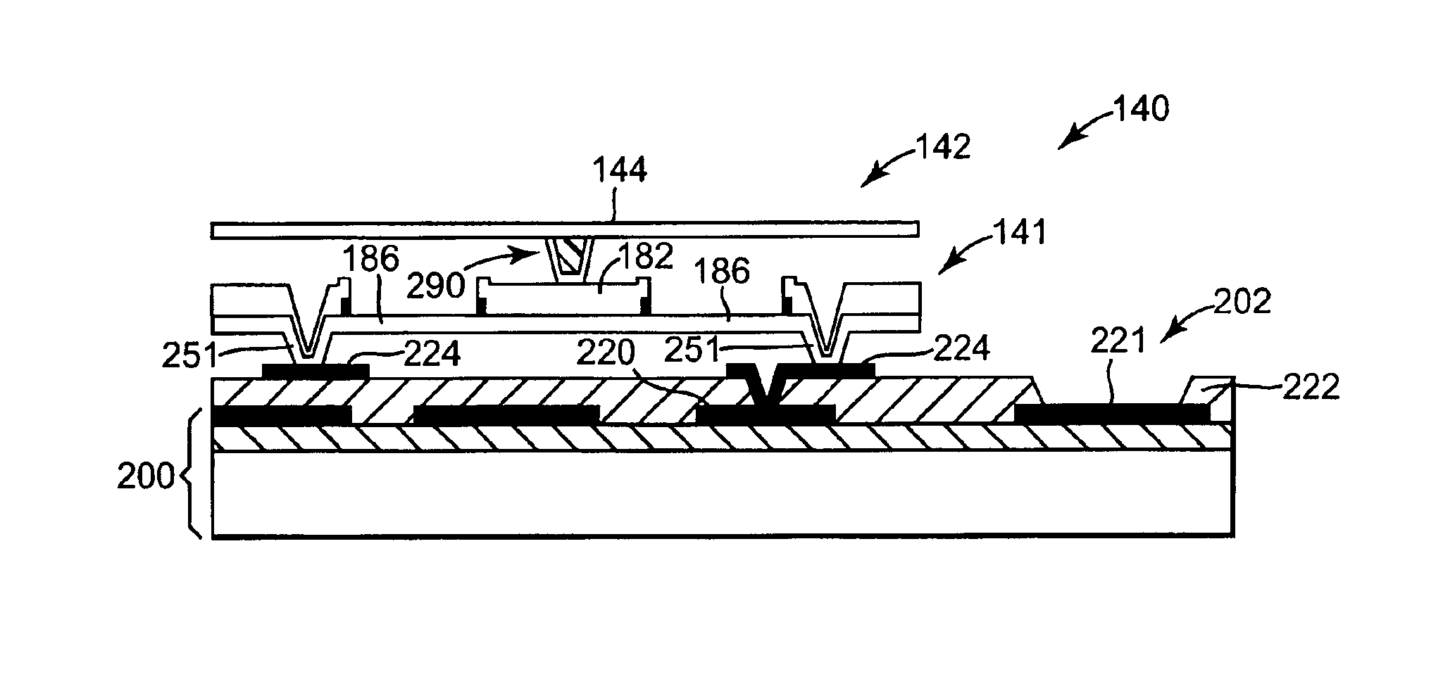
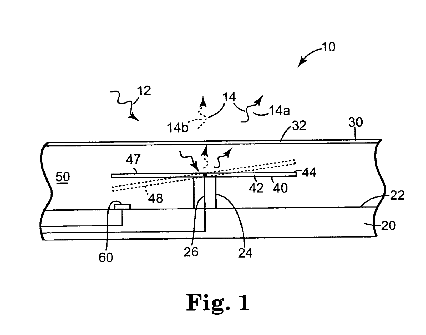
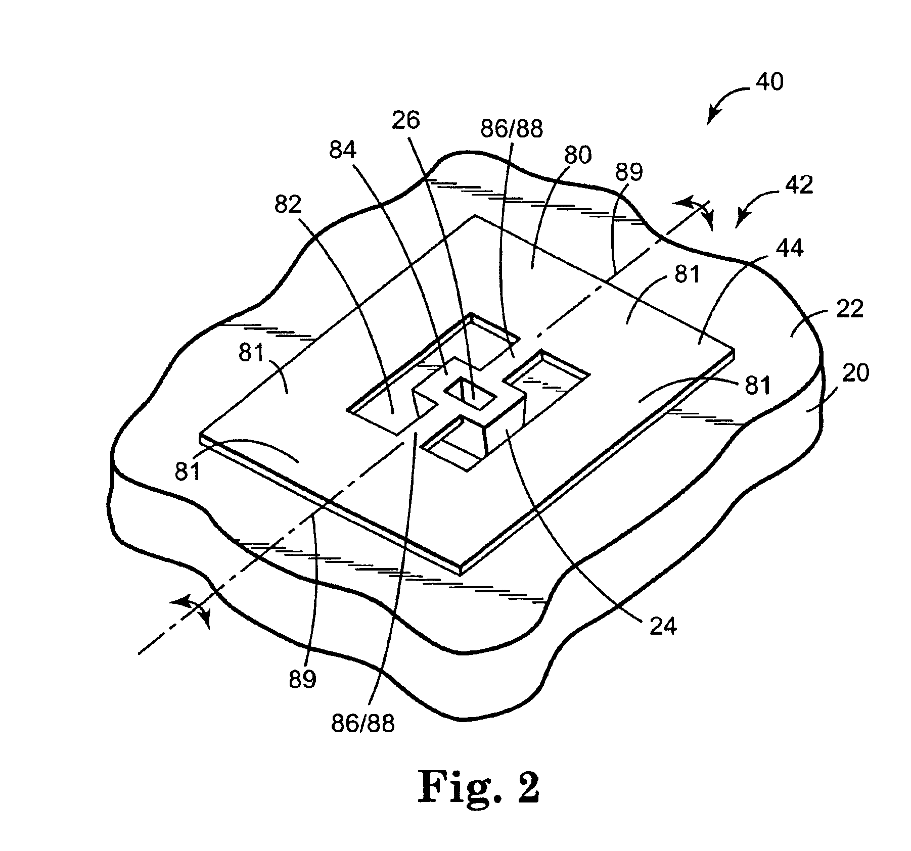
FIG. 1 illustrates one embodiment of a micro-mirror device 1...


PUM

PropertyMeasurementUnit
conductiveaaaaaaaaaa
semi-conductoraaaaaaaaaa
electromagneticaaaaaaaaaa

Abstract

A method of forming a MEMS device includes depositing a conductive material on a substructure, forming a first sacrificial layer over the conductive material, including forming a substantially planar surface of the first sacrificial layer, and forming a first element over the substantially planar surface of the first sacrificial layer, including communicating the first element with the conductive material through the first sacrificial layer. In addition, the method includes forming a second sacrificial layer over the first element, including forming a substantially planar surface of the second sacrificial layer, forming a support through the second sacrificial layer to the first element after forming the second sacrificial layer, including filling the support, and forming a second element over the support and the substantially planar surface of the second sacrificial layer. As such, the method further includes substantially removing the first sacrificial layer and the second sacrificial layer, thereby supporting the second element relative to the first element with the support.

Description

BACKGROUNDMicroelectromechanical systems or MEMS devices include micromachined substrates integrated with electronic microcircuits. Such devices may form, for example, microsensors or microactuators which operate based on, for example, electromagnetic, electrostrictive, thermoelectric, piezoelectric, or piezoresistive effects. MEMS devices have been formed on insulators or other substrates using micro-electronic techniques such as photolithography, vapor deposition, and etching.An example of a MEMS device includes a micro-mirror device. The micro-mirror device can be operated as a light modulator for amplitude and / or phase modulation of incident light. One application of a micro-mirror device is in a display system. As such, multiple micro-mirror devices are arranged in an array such that each micro-mirror device provides one cell or pixel of the display.A conventional micro-mirror device includes an electrostatically actuated mirror supported for rotation about an axis of the mirro...

Claims


Application Information

Patent Timeline
Patent Type & Authority Patents(United States)
IPC IPC(8): B81B3/00G02B26/08B81C1/00
CPCB81B3/0083G02B26/0841B81B2201/042Y10S359/904B81B2203/058B81B2203/0181
Inventor MONROE, MICHAEL G.NIKKEL, ERIC L.LAZAROFF, DENNIS M.
Owner TAIWAN SEMICON MFG CO LTD
Why Eureka
Try Eureka