Conducting structure and electronic clinical thermometer embodying the structure

a technology of electronic clinical thermometers and conductors, applied in the field of conductors and electronic clinical thermometers embodying the structure, can solve the problems of difficult affixing of metal heads to the body, inability to provide satisfactory heat balance effect, and metal heads cannot be in full contact with the human body, etc., and achieve the effect of being held easily and comfortably

Inactive Publication Date: 2008-01-22
ACTHERM INC
View PDF8 Cites 331 Cited by
  • Summary
  • Abstract
  • Description
  • Claims
  • Application Information

AI Technical Summary

Benefits of technology

[0011]It is the primary object of the present invention to provide an a conducting structure of an electronic clinical thermometer which can be in full contact with the skin of a human body, wherein the measuring end has a recess, a temperature sensor and conducting wires fitted in the recess, and a contact member having a curved top and made of metallic conductive material and having a predetermined length embedded in the recess thereby providing the contact member with a large temperature sensing contact area but only with a small portion protruded out of the measuring end, and therefore enabling the thermometer to be fully in contact with the human body, preventing the thermometer from being broken, and achieving heat balance rapidly.
[0012]It is another object of the present invention to provide an electronic clinical thermometer which can be held easily and comfortably, wherein the measuring end of the thermometer may be bent at a predetermined angle or the contact member may be arranged at either side of the measuring end as required so as to achieve the effect of sensing and conducting in full contact with the human body.

Problems solved by technology

However, since the metal head is fixedly fitted on the measuring end of the body portion with its surface almost completely exposed, the conventional electronic clinical thermometer suffers from the following drawbacks:1. The metal head is easily broken and detached from the body portion;2. The length of the metal head protruded from the body portion is larger than the length of the metal head embedded into the body portion thereby making it difficult to affix the metal head to the body portion according to the physical principle.3. The metal head is an elongated cylindrical member so that the area of the top for sensing temperature is relatively small thereby making it impossible to provide a satisfactory heat balance effect.
Furthermore, the body portion of the conventional clinical thermometer does not have any angular variation in shape, so that it will be very inconvenient and the metal head cannot be in full contact with the human body when measuring the temperature of the armpit.

Method used


Image

  • Conducting structure and electronic clinical thermometer embodying the structure
  • Conducting structure and electronic clinical thermometer embodying the structure
  • Conducting structure and electronic clinical thermometer embodying the structure

Examples


Embodiment Construction

[0024]The following descriptions are of exemplary embodiments only, and are not intended to limit the scope, applicability or configuration of the invention in any way. Rather, the following description provides a convenient illustration for implementing exemplary embodiments of the invention. Various changes to the described embodiments may be made in the function and arrangement of the elements described without departing from the scope of the invention as set forth in the appended claims.

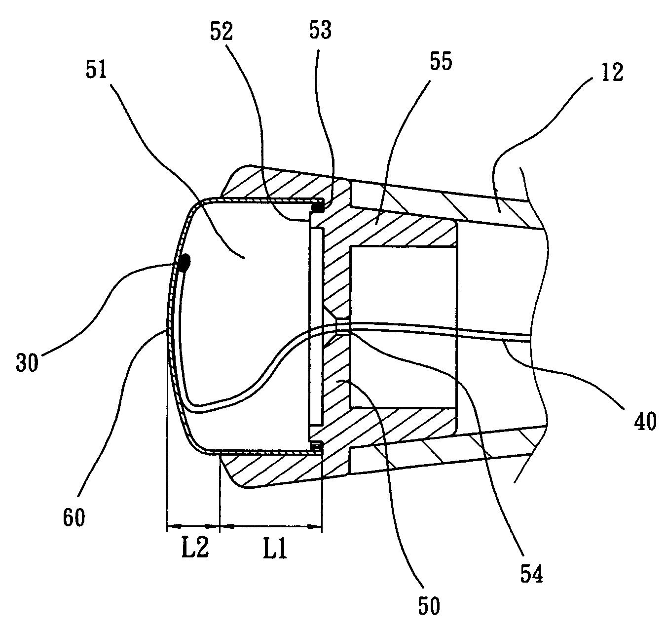
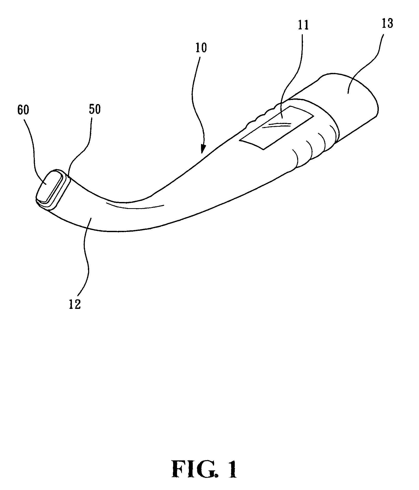
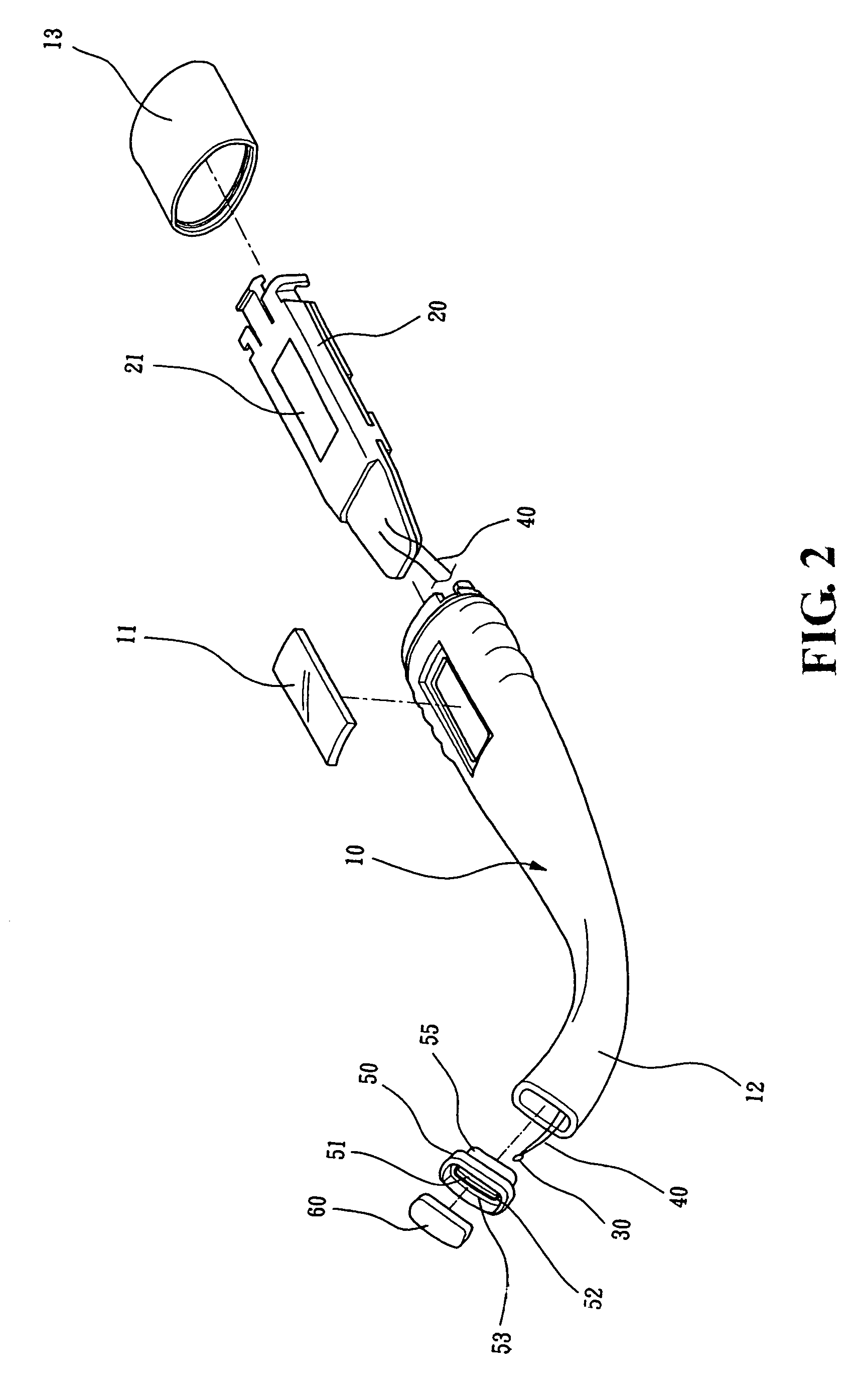
[0025]Referring to FIGS. 1, 2 and 3, the conducting structure according to the present invention is applied to an electronic clinical thermometer which comprises a body 10, a core 20, a temperature sensor 30 and conducting wires 40.

[0026]The body 10 is provided with a window 11 on the top side for viewing the temperature reading shown in the display 21. The body 10 is provided with a measuring end 12 provided with a conducting structure at an end and a detachable and waterproof cap 13 at the othe...


PUM

PropertyMeasurementUnit
conductingaaaaaaaaaa
lengthaaaaaaaaaa
areaaaaaaaaaaa

Abstract

A conducting structure and an electronic clinical thermometer, wherein the conducting structure is provided on the measuring end of the clinical thermometer, and the measuring end has a recess, a temperature sensor and conducting wires fitted in the recess, and a contact member having a curved top and made of metallic conductive material and having a predetermined length embedded in the recess thereby providing the contact member with a large temperature sensing contact area but only with a small portion protruded out of the measuring end, and therefore enabling the thermometer to be fully in contact with a certain portion of the human body such as the armpit, preventing the thermometer from being broken, and achieving heat balance rapidly. The measuring end of the thermometer may be bent at a predetermined angle or the contact member may be arranged at either side of the measuring end as required.

Description

BACKGROUND OF THE INVENTION[0001]1. Field of the Invention[0002]This invention is related to a conducting structure and an electronic clinical thermometer embodying the structure, and in particular to a conducting structure which includes a contact member having a curved top and made of metallic conductive material and having a predetermined length embedded in a recess of a measuring end of the clinical thermometer thereby providing the contact member with a large temperature sensing contact area but only with a small portion protruded out of the measuring end, and therefore enabling the clinical thermometer to be in full contact with the human body, preventing the clinical thermometer from being broken, and achieving heat balance rapidly, wherein the measuring end of the clinical thermometer embodying the conducting structure may be bent at a predetermined angle or the contact member may be arranged at either side of the measuring end as required so as to achieve the effect of sens...

Claims


Application Information

Patent Timeline
Patent Type & Authority Patents(United States)
IPC IPC(8): G01K1/00
CPCG01K1/16G01K13/002G01K13/20
Inventor HSIEH, CHIH-WEI
Owner ACTHERM INC
Why Eureka
Try Eureka