Composite porous current collector, and preparation method and application thereof

A technology of porous current collector and pore size, applied in electrical components, battery electrodes, circuits, etc., can solve problems affecting battery safety performance, battery short circuit, etc. Effect

Active Publication Date: 2015-12-23
南京竞予能源有限公司
View PDF6 Cites 50 Cited by
  • Summary
  • Abstract
  • Description
  • Claims
  • Application Information

AI Technical Summary

Problems solved by technology

However, this design also brings new problems: due to the close contact between the porous collector layer and the separator, when the battery is cycled or overcharged and overdischarged for many times, the porous collector layer of the negative electrode is in close contact with the separator. Lithium dendrites may be formed on one side, piercing the isolation layer and causing an internal short circuit in the battery, affecting the safety performance of the battery, especially when the isolation layer is a low-strength material such as sol-gel, this problem is more prominent

Method used


Image

  • Composite porous current collector, and preparation method and application thereof
  • Composite porous current collector, and preparation method and application thereof
  • Composite porous current collector, and preparation method and application thereof

Examples


Embodiment 1

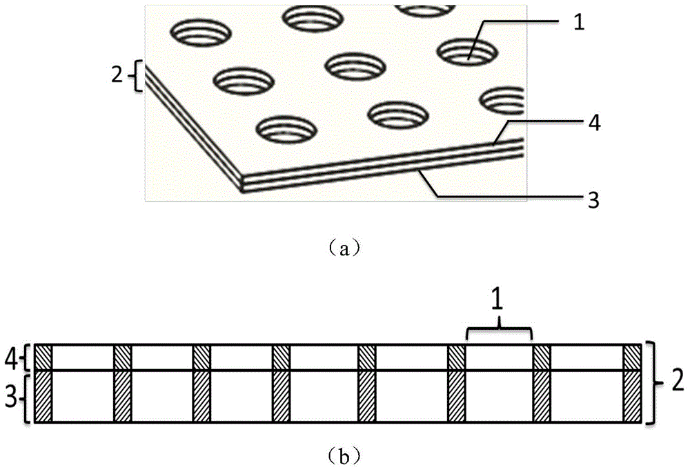
[0043] In this embodiment, the composite porous current collector includes: the electronic insulating layer 4 is a polyethylene film with a thickness of 30 μm, the porous electronic conductive layer 3 is a porous PET conductive cloth with a pore diameter of 300 to 800 μm, a porosity of 80%, and a thickness of 500 μm coated with carbon. .

[0044] The preparation method of the composite porous current collector of this embodiment is as follows:

[0045] 1) Pretreatment, specifically including:

[0046] a. Cleaning and drying: At room temperature, soak the carbon-coated porous PET conductive cloth in ethanol, acetone and dimethyl carbonate respectively and ultrasonically for 10 minutes to remove oil, dust and soluble impurities, and then rinse with deionized water Clean and dry under hot air at 90°C for 60 minutes.

[0047] At room temperature, soak the polyethylene film in acetone for 10 minutes to remove oil and dust on the surface, then rinse it with deionized water, and dr...

Embodiment 2

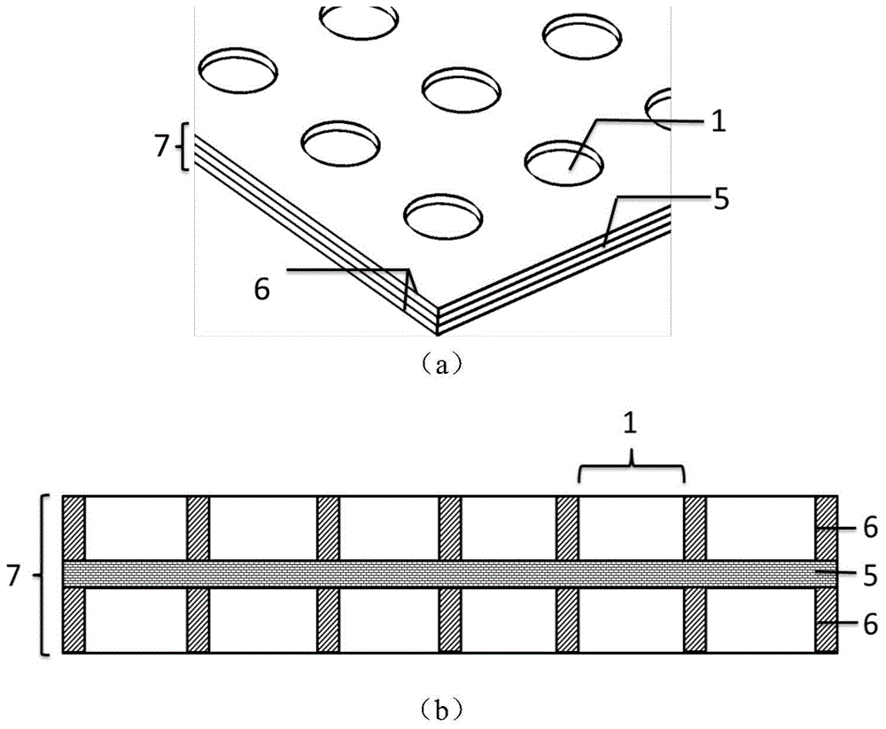
[0053] In this embodiment, the composite porous current collector includes: the electronic insulating layer 4 is a polyvinylidene fluoride film after the solution has been volatilized, and the thickness is 40 μm; Carbon porous PET conductive cloth.

[0054] The preparation method of the composite porous current collector of this embodiment is as follows:

[0055] 1) Pretreatment, specifically including:

[0056] a. Cleaning and drying: At room temperature, soak the carbon-coated porous PET conductive cloth in ethanol, acetone and dimethyl carbonate respectively and ultrasonically for 10 minutes to remove oil, dust and soluble impurities, and then rinse with deionized water Clean and dry under hot air at 90°C for 60 minutes.

[0057] b. Surface treatment: In order to increase the bonding strength between the porous PET conductive cloth and the polyvinylidene fluoride film and improve the interface performance, the cleaned and dried porous PET conductive cloth was treated in a...

Embodiment 3

[0062]In this embodiment, the composite porous current collector includes: the electronic insulating layer 4 is a polyethylene film with a thickness of 50 μm, and the porous electronic conductive layer 3 is a 200-mesh stainless steel mesh.

[0063] The preparation method of the composite porous current collector of this embodiment is as follows:

[0064] 1) Pretreatment, specifically including:

[0065] a. Cleaning and drying: Soak the stainless steel mesh in acetone at 40°C for 10 minutes to remove oil and dust on the surface, then rinse it with deionized water, and dry it under hot air at 90°C for 30 minutes.

[0066] At room temperature, soak the polyethylene film in acetone for 10 minutes to remove oil and dust on the surface, then rinse it with deionized water, and dry it under hot air at 60°C for 30 minutes.

[0067] b. Surface treatment: In order to increase the bonding strength between the stainless steel mesh and the polyethylene film and improve the interface perfor...


PUM

PropertyMeasurementUnit
thicknessaaaaaaaaaa
pore sizeaaaaaaaaaa
thicknessaaaaaaaaaa

Abstract

The invention provides a composite porous current collector, and a preparation method and an application thereof. The composite porous current collector comprises a porous electron conducting layer with through holes and an electron insulating layer with through holes, wherein the porosity of the through holes of porous electron conducting layer is not less than the porosity of the through holes of the electron insulating layer, a position of the porous electron conducting layer corresponding to the position of the through hole of the electron insulating layer is a through hole, and a position of the porous electron conducting layer corresponding to the position of the non-through hole of the electron insulating layer can be a through hole, and also can be a blind hole or a rough surface. The electron insulating layer is adjacent to an isolation layer, so puncture of precipitated lithium dendrite to a diaphragm is prevented, direct contact of the electron conducting layer is avoided, and the safety of a battery is improved; the above corresponding through hole structure is in favor of transferring lithium ions, so the internal resistance of the battery is reduced; the hole structure of the porous electron conducting layer and the homogeneous rough surface are in favor of full contact of an electrode active substance with the current collector, the current is uniformly distributed, and the current collection effect is improved; and the preparation method adopting airflow punching has the advantages of simplicity, easy implementation, cleanness, energy saving, combination of other various enforcement modes, and convenience for production and application.

Description

technical field [0001] The invention belongs to the technical field of lithium-ion flow batteries, and mainly relates to a composite porous current collector for lithium-ion flow batteries and its preparation method and application. Background technique [0002] Lithium-ion flow battery is a newly developed chemical battery technology. It combines the advantages of lithium-ion battery and flow battery. It is a new type of battery with independent output power and energy storage capacity, high energy density and low cost. rechargeable battery. The battery reaction chamber is an important part of the lithium-ion flow battery reactor. In traditional lithium-ion flow batteries, the battery reaction chamber is formed by the gap between the current collector layer and the isolation layer. Because the distance between the battery reaction chamber is too large, the conductive distance between electrons and ions in the electrode suspension will be increased, which will increase the ...

Claims


Application Information

Patent Timeline
Patent Type & Authority Applications(China)
IPC IPC(8): H01M4/86H01M4/88
CPCY02E60/50
Inventor 陈永翀何颖源张艳萍张萍
Owner 南京竞予能源有限公司
Why Eureka
Try Eureka