Motor vehicle door lock

A technology of motor vehicle door locks and rotating lock forks, which is applied in the direction of electric vehicle locks, vehicle locks, building locks, etc., to achieve the effect of compact cost

Active Publication Date: 2017-07-04
KIEKERT AG
View PDF5 Cites 0 Cited by
  • Summary
  • Abstract
  • Description
  • Claims
  • Application Information

AI Technical Summary

Problems solved by technology

Such a design can be implemented without difficulty in known and relatively complex and bulky locking pawls, but problems arise when special pawl arrangements have to be followed

Method used


Image

  • Motor vehicle door lock

Examples


Embodiment Construction

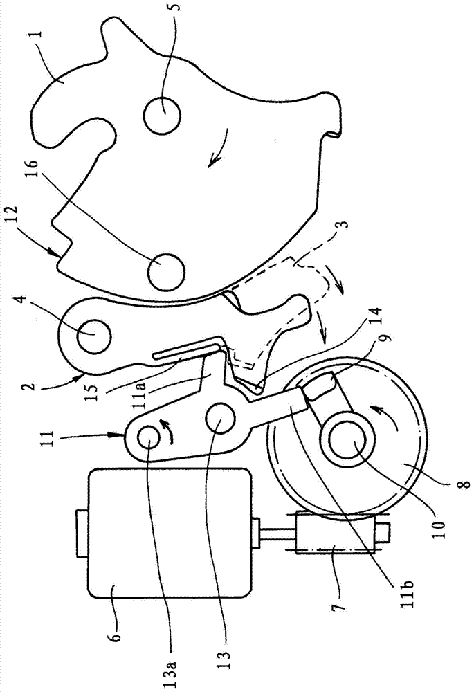
[0026] The single figure shows a motor vehicle door lock which is generally equipped with a locking mechanism 1 , 2 , 3 which essentially consists of a rotary latch 1 and one or more pawls 2 , 3 . The locking mechanism 1 , 2 , 3 interacts with a not shown locking pin, which may be arranged on the body of the motor vehicle. In contrast, the motor vehicle door locks shown in the figures are usually located inside the motor vehicle door, in the exemplary embodiment inside the rear hatch. That is to say, the present exemplary embodiment relates to a tailgate lock, which in principle can also be used in a side door of a motor vehicle, ie can be designed as a side door lock.

[0027] According to the single figure, it can be seen that the locking mechanism 1 , 2 , 3 consists of the already described rotary locking fork 1 and the two locking pawls 1 , 2 , which is only an example and (the invention) is not restricted to this case. Thus only the first locking pawl 2 or the comfort pa...


PUM


Abstract

The invention relates to a motor vehicle door lock, which has a locking mechanism (1, 2, 3) mainly composed of a rotary locking fork (1) and at least one locking pawl (2, 3) for locking the Drive means (6 to 9) acting on the mechanism (1, 2, 3), locking element (11) interacting with the locking pawl (2, 3), the locking element having at least one locking pawl arm (11a) , the locking pawl arm keeps the locking pawl (2, 3) in the blocking position, the motor vehicle door lock also has a locking element (11) and / or on the locking pawl (2, 3) and / or on the triggering Stop arm ( 11 b ) on the element for stopping the drive ( 6 to 9 ), characterized in that the blocking element ( 11 ) is arranged at the edge remote from the rotary locking fork and is connected to the locking The claws (2, 3) overlap laterally.

Description

technical field [0001] The invention relates to a motor vehicle door lock having a locking mechanism consisting essentially of a rotary locking fork and at least one locking pawl, a drive device for acting on the locking mechanism, a locking mechanism interacting with the locking pawl The locking element has at least one pawl arm, which holds the pawl in the locked position, and a drive arm, which serves to stop the drive. The drive arm or stop arm is arranged on the blocking element and / or on the pawl and / or on the trigger element. Background technique [0002] A motor vehicle door lock of the aforementioned construction is described in DE 103 12 093 B4. This is a rotary cleat lock in which the pawl is transferred by means of a control element by means of an electric motor as drive into the released position of the pawl. This is the normal function of what is known as "electric opening". [0003] In the case of a so-called failure to open, the turning catch, although rel...

Claims


Application Information

Patent Timeline
Patent Type & Authority Patents(China)
IPC IPC(8): E05B81/14E05B85/26
CPCE05B81/14E05B85/26E05B77/36E05B79/10E05B85/243
Inventor M·史古茨O·格策
Owner KIEKERT AG
Why Eureka
Try Eureka