Full-automatic punching die

A fully automatic, punching technology, applied in the field of punching dies, can solve the problem of inaccurate positioning

Inactive Publication Date: 2016-01-27
滁州市成业机械制造股份有限公司
View PDF6 Cites 7 Cited by
  • Summary
  • Abstract
  • Description
  • Claims
  • Application Information

AI Technical Summary

Problems solved by technology

[0002] Punching die is one of the more common and widely used molds. Its main purpose is to punch holes in the parts according to the actual use needs after the production of parts is completed, so as to facilitate the subsequent installation process. Therefore, the punching die is good It is related to the accuracy of punching and the quality of the corresponding parts. At present, conventional punching dies are positioned manually, which is often not accurate enough. With the continuous improvement of factory automation, fully automatic punching dies can be designed

Method used


Image

  • Full-automatic punching die

Examples


Embodiment Construction

[0014] Below in conjunction with accompanying drawing and embodiment the invention is described in detail:

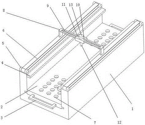
[0015] The invention provides a fully automatic punching die, which drives the bracket to move through the transmission, and drives the punching equipment to move horizontally through the motor of the bracket, thereby realizing fully automatic punching. After using the punching die, the punching is accurate and continuous punching can be realized. hole.

[0016] As an embodiment of the present invention, the present invention provides a fully automatic punching die, including a chassis 1, a pull plate 2, a main motor 5, a transmission belt 6, a bracket 8, a moving bracket 10, a punch 12 and a moving motor 13, The section of the underframe 1 is U-shaped, the inner walls of the two side ends of the underframe 1 have guide rails, the two side ends of the pull plate 2 are clamped in the guide rails, and the upper parts of the two side ends of the underframe 1 Each has a pa...


PUM


Abstract

The invention discloses a full-automatic punching die. The section of a bottom frame of the full-automatic punching die is U-shaped; inner walls of two side ends of the bottom frame are provided with guide rails; two ends of a pulling plate are clamped into the guide rails; the upper parts of the two side ends of the bottom frame are each provided with a pair of primary motors; two transmission belts are respectively arranged on rotary shafts of corresponding primary motors; two side bottom ends of a bracket are fixed on the corresponding transmission belts; two groups of fixing holes are formed in the pulling plate; each group of fixing holes comprises at least two rows of fixing holes; a guide rail slot is formed in the bracket; a movable bracket is arranged on the bracket in a sleeving mode; the bottom of the movable bracket is provided with a punch; the movable bracket is provided with a movable motor; a rotary shaft of the movable motor penetrates through the movable bracket to the guide rail slot; a limiting part is arranged at each of two sides of the movable motor; and the limiting parts penetrate through the movable bracket to the guide rail slot. According to the full-automatic punching die provided by the invention, full-automatic movement of punching equipment is realized by virtue of the corresponding structures, so that precise punching and positioning are guaranteed, and punching effect is good.

Description

technical field [0001] The invention relates to the field of punching dies, in particular to a fully automatic punching die. Background technique [0002] Punching die is one of the more common and widely used molds. Its main purpose is to punch holes in the parts according to the actual use needs after the production of parts is completed, so as to facilitate the subsequent installation process. Therefore, the punching die is good It is related to the accuracy of punching and the quality of corresponding parts. At present, conventional punching dies are positioned manually, which is often not accurate enough. With the continuous improvement of factory automation, fully automatic punching dies can be designed. Contents of the invention [0003] In view of the above problems, the present invention provides a fully automatic punching die, which can realize the automatic movement of the punching equipment through the corresponding structure, thereby ensuring accurate punc...

Claims


Application Information

Patent Timeline
Patent Type & Authority Applications(China)
IPC IPC(8): B21D28/34B26F1/14
Inventor 张志
Owner 滁州市成业机械制造股份有限公司
Why Eureka
Try Eureka