
A Method for Checking Hole Center Offset

An inspection method and center-of-circle technology, applied in metal processing equipment, measuring/indicating equipment, metal processing mechanical parts, etc., can solve the problems of high requirements, long assembly time, waste, etc., and achieve the effect of low cost and fast operation

Active Publication Date: 2017-11-14
GUANGZHOU SHIPYARD INTERNATIONAL LTD
View PDF7 Cites 0 Cited by
  • Summary
  • Abstract
  • Description
  • Claims
  • Application Information

AI Technical Summary

Problems solved by technology

[0003] However, the steps of the above method are too cumbersome and the efficiency is low; the combination ruler or steel ruler used has high requirements, if there is wear and tear, the test results will be affected, and the measuring tools need to be replaced continuously, resulting in waste; in addition, the parts are in difficult positions. When, too many steps make the operation difficult and the efficiency is lower
[0004] In addition, during assembly, it is necessary to locate the center of the hole before assembling. Due to the cumbersome marking of the prior art, the assembly time is long and the efficiency is low.

Method used


Image

  • A Method for Checking Hole Center Offset
  • A Method for Checking Hole Center Offset
  • A Method for Checking Hole Center Offset

Examples


Embodiment 1

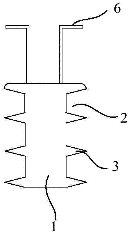
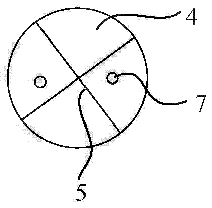
[0034] Such as figure 1 and 2 As shown, a fast marking and positioning device for the center of a hole includes a polyurethane round rod 1 that can be inserted into the hole 8. The outer diameter of the polyurethane round rod 1 is larger than the diameter of the hole 8, and the side wall of the polyurethane round rod 1 is provided with concave holes. Groove 2, because polyurethane material has flexibility, when inserting hole 8, even if the outer diameter of polyurethane round rod 1 is larger than the diameter of hole 8, under the situation that groove 2 exists, the side wall of polyurethane round rod 1 can realize deformation or Bending, so that the polyurethane round rod 1 can be inserted into the hole 8, and ensure a close fit with the hole 8. Specifically, the outer diameter of the polyurethane round rod 1 is 0-0.5mm larger than the diameter of the hole 8, which is easy to operate and has a good matching effect; The upper end surface 4 of the polyurethane round rod 1 is e...

Embodiment 2

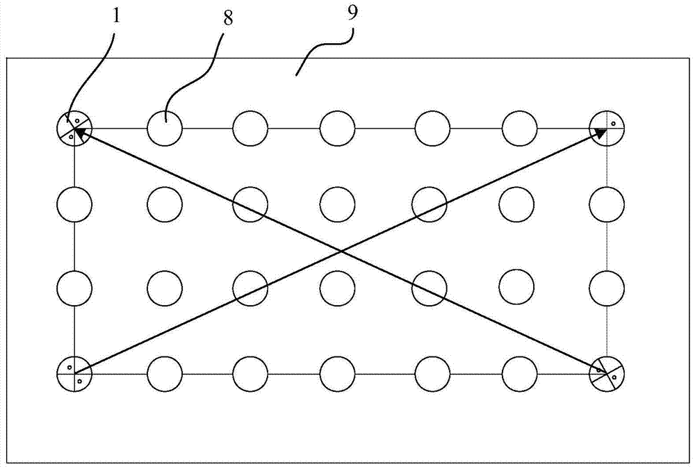
[0039] This embodiment protects a method for checking hole center offset, specifically using a hole center quick marking positioning device for checking, including the following steps,

[0040] Step 1, select at least two identical devices;

[0041] Step 2, inserting the devices into different holes 8 on the part 9 with holes, so that the upper end surface 4 of the device is flat with the surface of the part 9;

[0042] Step 3, according to the different arrangements of the holes 8, select the center of circle of the upper end surface 4 connected to the same row or the opposite device, and check whether the center of the hole on the same straight line as the two interconnected devices is offset;

[0043] Step 4, repairing the offset holes 8 to meet application requirements.

[0044] Further, in step 2, the specific arrangement of the device is not limited, it is only necessary to check whether the center of the hole is offset, specifically, as image 3 As shown, any two devi...


PUM


Abstract

The invention discloses a hole centre rapid marking-positioning device and a hole centre bias check method, and relates to the technical field of hole centre marking. The hole centre rapid marking-positioning device comprises polyurethane round rods capable of inserting in holes, wherein the outer diameter of each polyurethane round rod is greater than the diameter of the corresponding hole; grooves are formed in the sidewall of each polyurethane round rod; and cross lines with an intersection point which passes through the circle centre of the upper end surface are engraved on the upper end surface of each polyurethane round rod. The invention further discloses a hole centre bias check method, and said hole centre check device is used for check. The hole centre rapid marking-positioning device and the hole centre bias check method, which are disclosed by the invention, are capable of realizing rapid marking-positioning for hole centres, capable of conveniently and rapidly detecting whether the hole centres are biased or not, high in detection accuracy, and suitable for being applied in various construction fields.

Description

technical field [0001] The invention relates to the field of hole center scribing technology, in particular to a hole center fast scribing positioning device and a hole center offset inspection method. Background technique [0002] The steel structure and shipbuilding industry are inseparable from the bolted structure. Most of the structures connected by bolts are provided with multiple holes in rows. First, the holes need to be drilled, and after drilling, it is necessary to check whether there is any deviation in these holes. In the prior art, detection is mainly carried out by multi-step scribing with a combination ruler or a steel ruler. [0003] However, the steps of the above method are too cumbersome and the efficiency is low; the combination ruler or steel ruler used has high requirements, if there is wear and tear, the test results will be affected, and the measuring tools need to be replaced continuously, resulting in waste; in addition, the parts are in difficult ...

Claims


Application Information

Patent Timeline
Patent Type & Authority Patents(China)
IPC IPC(8): B23Q17/20
CPCB23Q17/20
Inventor 唐合成杨茨祥冷如松何志敏
Owner GUANGZHOU SHIPYARD INTERNATIONAL LTD
Learn More