Hole centre rapid marking-positioning device and hole centre bias check method
A technology of positioning device and inspection method, applied in metal processing equipment, measuring/indicating equipment, metal processing mechanical parts, etc., can solve the problems of high requirements, long assembly time, influence of inspection results, etc. Effect
- Summary
- Abstract
- Description
- Claims
- Application Information
AI Technical Summary
Problems solved by technology
Method used
Image
Examples
Embodiment 1
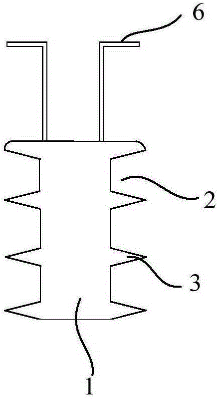
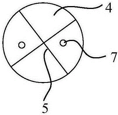
[0034] Such as figure 1 with 2 As shown, a quick scribing positioning device for the center of a hole includes a polyurethane round rod 1 that can be inserted into the hole 8. The outer diameter of the polyurethane round rod 1 is larger than the diameter of the hole 8, and the side wall of the polyurethane round rod 1 is provided with a concave Groove 2, due to the flexibility of the polyurethane material, when inserted into the hole 8, even if the outer diameter of the polyurethane rod 1 is larger than the diameter of the hole 8, in the presence of the groove 2, the side wall of the polyurethane rod 1 can be deformed or Bending enables the polyurethane round rod 1 to be inserted into the hole 8 and ensures a close fit with the hole 8. Specifically, the outer diameter of the polyurethane round rod 1 is 0-0.5mm larger than the diameter of the hole 8, which is convenient to operate and has a good matching effect; The upper end surface 4 of the polyurethane round rod 1 is engraved ...
Embodiment 2
[0039] This embodiment protects a hole center deviation inspection method. Specifically, the inspection is performed by using a hole center quick marking positioning device, which includes the following steps:
[0040] Step 1: Select at least two identical devices;
[0041] Step 2: Insert the device into different holes 8 on the part 9 with holes, so that the upper end surface 4 of the device is level with the surface of the part 9;
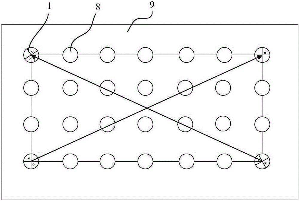
[0042] Step 3: According to the different arrangement of the holes 8, select the center of the upper end surface 4 connecting the same row or opposite devices, and check whether the hole centers on the same straight line with the two devices connected to each other are offset;
[0043] Step 4: Repair the offset hole 8 to meet application requirements.
[0044] Further, in step 2, the specific arrangement of the device is not limited, and it is sufficient to check whether the center of the hole is offset, specifically, such as image 3 As shown, any two dev...
PUM
 Abstract
Description
Claims
Application Information
 - R&D
- Intellectual Property
- Life Sciences
- Materials
- Tech Scout
- Unparalleled Data Quality
- Higher Quality Content
- 60% Fewer Hallucinations
Browse by: Latest US Patents, China's latest patents, Technical Efficacy Thesaurus, Application Domain, Technology Topic, Popular Technical Reports.
© 2025 PatSnap. All rights reserved.Legal|Privacy policy|Modern Slavery Act Transparency Statement|Sitemap|About US| Contact US: help@patsnap.com


