Electric breaker spring disassembly device

A technology for dismantling devices and circuit breakers, which is applied to hand-held tools, manufacturing tools, etc., can solve the problems of time-consuming, uneven spring force, and long spring dismantling time.

Inactive Publication Date: 2016-02-03
国网山东莒南县供电公司 +1
View PDF6 Cites 14 Cited by
  • Summary
  • Abstract
  • Description
  • Claims
  • Application Information

AI Technical Summary

Problems solved by technology

Due to the compact design, the space of the mechanism box is narrow and there is no force point to stretch the spring. It takes time and effort to disassemble the spring, and it is even impossible to disassemble the spring. In the past, the maintenance personnel disassembled the spring by inserting a certain number of gaskets into the spring and propping the spring to a certain length. The spring is removed, but this method will cause uneven force on the inner and outer sides of the spring. When disassembling the spring, the gasket may pop out and hurt people if you do not pay attention to it. The safety factor is low, and this method is time-consuming. The time to remove the spring is longer than replacing the damaged parts. longer time
[0003] The application date is 2014.03.23, and the patent document with the application number 201420130695.0 discloses a new type of auxiliary tool for energy storage spring disassembly and assembly, including two seesaws, a rotating rod and a support rod. The front end of the seesaw is provided with a flat cutting edge and a U-shaped opening to facilitate insertion into the gap when the spring is not storing energy. The rear end of the seesaw is provided with a screw cap integrated with the seesaw. The upper part of the rotating rod is in the same direction as the screw cap of the upward rocker. The wire direction of the lower part of the rotating rod is the same as that of the screw cap of the lower rocker, and the wire direction of the upper part is opposite to that of the lower part. The support rod forms a fulcrum connection to the middle positions of the upper and lower rockers. There are adjusting nuts at both ends of the support rod, which can be adjusted The length of the support rod is adapted to springs of different lengths, but the tool still has a problem: when the distance between the upper and lower rockers is adjusted through the rotating rod, when the angle of inclination is generated between the rotating rod and the upper and lower rockers , there is interference between the rotating rod and the upper and lower rocker nuts so that the adjustment cannot be continued, and there will also be interference between the support rod and the upper and lower rockers so that the adjustment cannot be continued. The adjustment range of this device is very limited

Method used


Image

  • Electric breaker spring disassembly device
  • Electric breaker spring disassembly device
  • Electric breaker spring disassembly device

Examples


Embodiment Construction

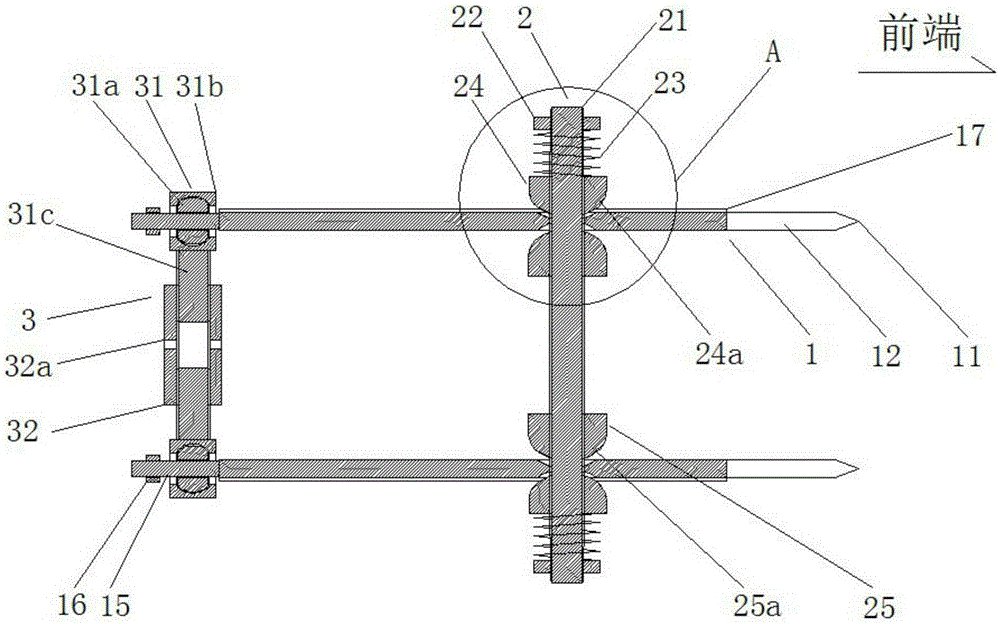
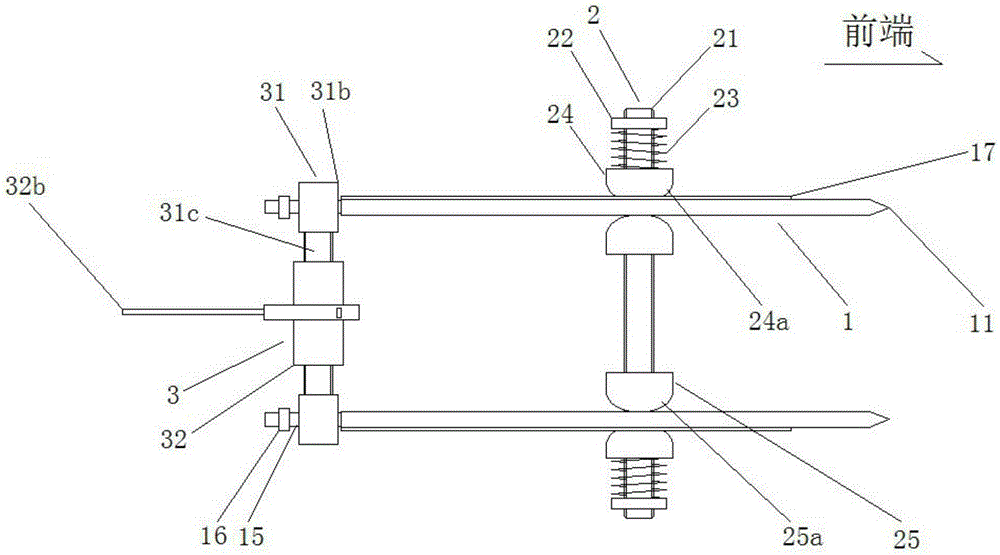
[0022] The present invention will be described in further detail below in conjunction with the accompanying drawings. It should be noted that the "front-end", "back-end" and Figure 1-Figure 2 Corresponds to the "front end" shown in .

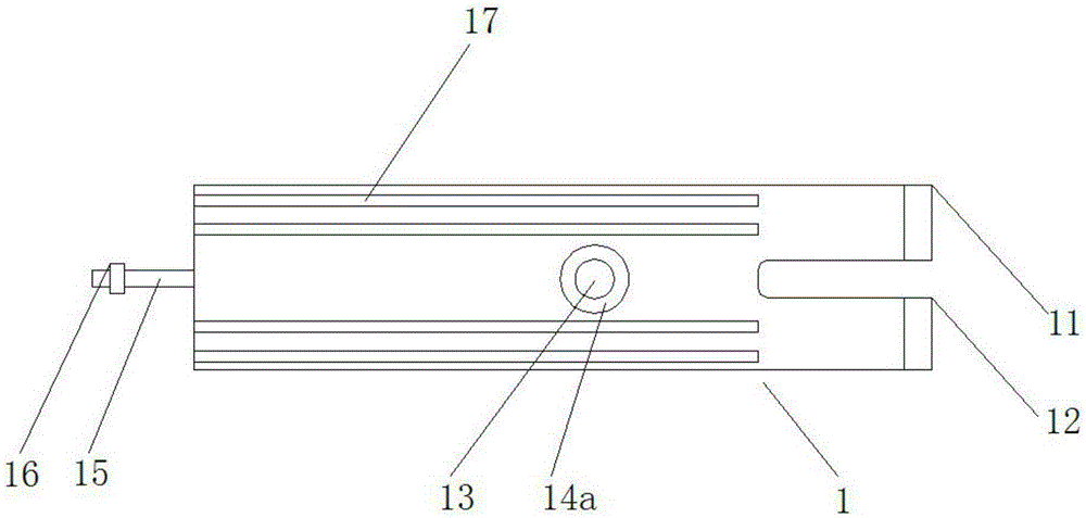
[0023] A spring removal device for a power circuit breaker, comprising a seesaw 1, a support rod 2, and an adjustment rod 3; two seesaws 1 are provided, and a pointed blade 11 is provided at the front end of the seesaw 1, and the seesaw 1. A "U"-shaped groove 12 is provided in the middle part of the front end, and a first through hole 13 is provided on the seesaw 1, which is characterized in that:

[0024] The parts where the end faces of the two seesaws 1 are far away from each other are located on the outer edge of the first through hole 13 are formed with an outer arc-shaped depression 14a, and the end faces of the two seesaws 1 that are close to each other are located on the outer edge of the first through hole 13. An inner arc-shaped dep...


PUM


Abstract

The invention relates to an electric breaker spring disassembly device. The electric breaker spring disassembly device comprises turning plates, a support rod and an adjusting rod, wherein two turning plates are provided; sharp edges are arranged at the front ends of the turning plates; U-shaped grooves are formed in the middle parts of the front ends of the turning plates; first through holes are formed in the turning plates; shaft rods are arranged at the back ends of the turning plates; first external threads are arranged at the tail ends of the shaft rods; the support rod comprises a screw rod, a pretightening nut, a compression spring, a bulb slide block and a bulb nut; the adjusting rod comprises joint shaft heads arranged on the shaft rod, and a connecting rod movably connected between two joint shaft heads; the joint shaft heads comprise inner rings, outer rings and connecting rods; and the first external threads at the tail ends of the shaft rods are provided with limiting nuts for limiting the joint shaft heads. When the turning plates have larger inclined angles with the adjusting rod and the support rod, the adjusting rod and the support rod still can be continuously used, so that the adjusting range is largely widened.

Description

technical field [0001] The invention relates to the technical field of electric circuit breakers, in particular to a spring removal device for electric circuit breakers. Background technique [0002] In recent years, switches with spring-type operating mechanisms have become more and more common in the field of power systems. This type of switch has a complex structure, and it is difficult to replace some parts, among which the disassembly of the spring is the most difficult. Due to the compact design, the space of the mechanism box is narrow and there is no force point to stretch the spring. It takes time and effort to disassemble the spring, and it is even impossible to disassemble the spring. In the past, the maintenance personnel disassembled the spring by inserting a certain number of gaskets into the spring and propping the spring to a certain length. The spring is removed, but this method will cause uneven force on the inner and outer sides of the spring. When disasse...

Claims


Application Information

Patent Timeline
Patent Type & Authority Applications(China)
IPC IPC(8): B25B27/30
CPCB25B27/30
Inventor 刘树军纪翔刘昊吴联盟魏华
Owner 国网山东莒南县供电公司
Why Eureka
Try Eureka