Lever mechanism of rail transit braking clamp

A technology of brake caliper and rail transportation, which is applied to the operating mechanism of railway vehicle brakes, railway braking systems, railway car body parts, etc., which can solve the problems of inconvenient operation, increased maintenance costs, and easy wear and tear, and improve efficiency , low maintenance cost and easy operation

Active Publication Date: 2016-02-03
CRRC CHANGZHOU TECH MARK IND CO LTD +1
View PDF8 Cites 2 Cited by
  • Summary
  • Abstract
  • Description
  • Claims
  • Application Information

AI Technical Summary

Problems solved by technology

[0002] The lever of the existing floating single-side acting brake caliper for rail transit is only composed of a lever body. In actual work, the contact area and contact angle between one end of the lever and the output shaft of the brake cylinder vary with the output shaft of the brake cylinder. It is changed by jacking up, so that the efficiency of the lever to transmit the braking force is low. When working, one end of the lever is frequently impacted by the output shaft of the brake cylinder, which is very easy to wear and tear. At the same time, the other end of the lever is in direct contact with the brake pad, which is also easy to wear , the entire lever needs to be replaced, which greatly increases the maintenance cost; and when there is a problem inside the clamp that needs to be relieved, it cannot be relieved manually, but the entire lever must be removed, which is very inconvenient to operate

Method used


Image

  • Lever mechanism of rail transit braking clamp
  • Lever mechanism of rail transit braking clamp
  • Lever mechanism of rail transit braking clamp

Examples


Embodiment Construction

[0034] The present invention will be further described below in conjunction with the accompanying drawings and the given embodiments.

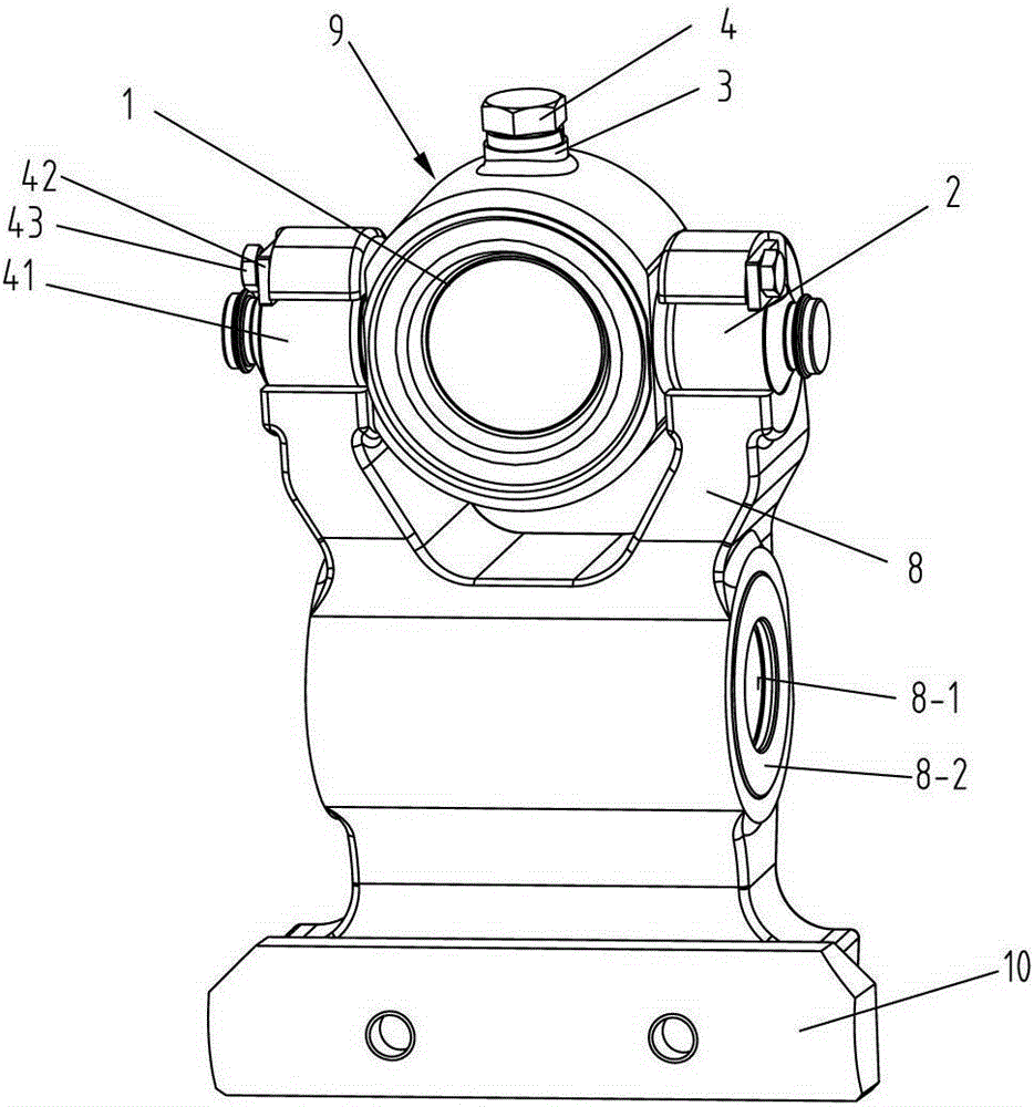
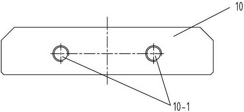
[0035] like Figures 1~9 As shown in , 12, a lever mechanism of a rail transit brake caliper has a lever body 8, a shaft hole 8-1 is opened in the middle of the lever body 8, and one end of the lever body 8 also has a top block mechanism 9, so The top block mechanism 9 has a top block body 1, and the top block body 1 has two coaxial connecting shafts 2. The connecting shafts 2 are assembled or integrated with the top block body 1, and are located in the top block body 1. The outer wall of the top block body 1 has a radial positioning hole 3-1, and the positioning hole 3-1 is threadedly connected with the limit screw 4; the top block body 1 is provided with a mounting hole 1 -1, the installation hole 1-1 is equipped with a fixed screw plug 5, the front part of the fixed screw plug 5 is threadedly connected with the internal thread of the insta...


PUM


Abstract

A lever mechanism of a rail transit braking clamp comprises a lever body. A shaft hole is formed in the middle of the lever body. An ejecting block mechanism is arranged at one end of the lever body and provided with an ejecting block body. The ejecting block body is provided with two coaxial connection shafts. A radial positioning hole is formed in the ejecting block body. The ejecting block body is provided with an installation hole. A fixing plug is arranged in the installation hole. A counter bore is formed in the front end face of the fixing plug. A pressing block is arranged in the counter bore. A cushion block is arranged at the other end of the lever body. After the lever mechanism is used for the rail transit braking clamp, the pressing block of the ejecting block mechanism and an output shaft of a brake cylinder can make contact of the maximum area all the time, and the braking force transmission efficiency is effectively improved. After the pressing block or the cushion block is abraded, only parts need to be replaced, and the maintenance cost is low; when faults happen, manual release can be achieved just by adjusting the fixing plug in the ejecting block mechanism, and operation is easy and convenient.

Description

technical field [0001] The invention belongs to the technical field of basic braking devices, and in particular relates to a lever mechanism of a rail transit brake caliper. Background technique [0002] The lever of the existing floating single-side acting brake caliper for rail transit is only composed of a lever body. It is changed by jacking up, so that the efficiency of lever transmission of braking force is low. When working, one end of the lever is frequently impacted by the output shaft of the brake cylinder, which is very easy to wear and tear. At the same time, the other end of the lever is in direct contact with the brake pad, which is also easy to wear and tear. , the entire lever needs to be replaced, which greatly increases the maintenance cost; and when there is a problem in the clamp that needs to be alleviated, it cannot be relieved manually, and the lever must be removed entirely, which is very inconvenient to operate. SUMMARY OF THE INVENTION [0003] T...

Claims


Application Information

Patent Timeline
Patent Type & Authority Applications(China)
IPC IPC(8): B61H13/34
Inventor 雷国伟王睿文朱君华韩红文霍伟
Owner CRRC CHANGZHOU TECH MARK IND CO LTD
Why Eureka
Try Eureka