
DDR controller low-power control circuit based on DFI interface

A technology for controlling circuits and controllers, which is applied in the direction of instruments, static memory, digital memory information, etc., and can solve the problem that dynamic power consumption cannot be controlled

Active Publication Date: 2016-02-03
XI AN UNIIC SEMICON CO LTD
View PDF4 Cites 2 Cited by
  • Summary
  • Abstract
  • Description
  • Claims
  • Application Information

AI Technical Summary

Problems solved by technology

[0002] see figure 1 As shown, the DDR control logic of the DDR controller and DDRPHY are connected through a standard DFI interface; when the DDR controller is in non-sleep mode (or task mode), due to the functional characteristics of the DDR controller, the clock of DDRPHY cannot be interrupted , dynamic power consumption cannot be controlled

Method used


Image

  • DDR controller low-power control circuit based on DFI interface
  • DDR controller low-power control circuit based on DFI interface

Examples


Embodiment Construction

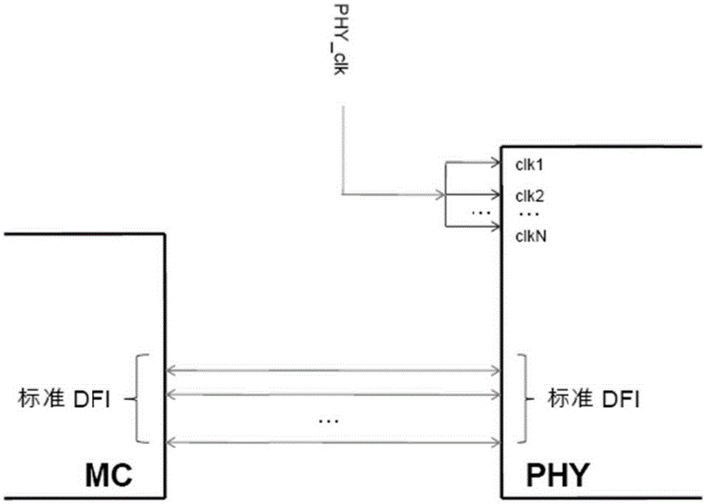
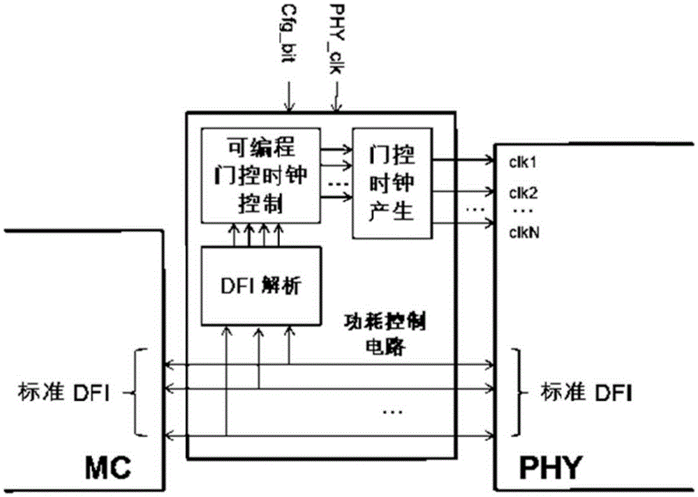
[0017] See figure 2 Shown is a preferred embodiment of the present invention. The power consumption control circuit is inserted between the DDR control logic and the DDRPHY in the DDR controller; the input end of the power consumption control circuit is connected to the DFI interface of the DDR control logic to obtain the DFI signal. The power consumption control circuit does not change the connection signal between the original DDR control logic and DDRPHY. The input end of the power consumption control circuit is also connected to the input clock signal PHY_clk that the system originally supplied to DDRPHY and the configuration signal Cfg_bit of the system; the output end of the power consumption control circuit is connected to DDRPHY.

[0018] The typical structure of the power control circuit includes a DFI analysis module, a programmable gated clock control module, and a gated clock generation module. The input terminal of the DFI analysis module is connected to the DFI o...


PUM


Abstract

The invention discloses a DDR controller low-power control circuit based on a DFI interface. The DDR controller low-power control circuit comprises a DFI parsing module, a programmable gated clock control module and a gated clock generation module. An input end of the DFI parsing module is connected to a DFI output end of DDR control logic in a DDR controller, and an output end of the DFI parsing module is connected to an input end of the programmable gated clock control module. An output end of the programmable gated clock control module is connected to an input end of the gated clock generation module. An output end of the gated clock generation module is connected to a DDR PHY. By parsing a DFI signal which is sent from DDR control logic in the DDR controller to the DDR PHY, several paths of gated clock control signals can be customized according to a programmable gated clock control strategy, so as to realize multiple paths of gated clock output. By classification control and supply of different clocks of logic circuit parts in the DDR PHY, logic state upset rate of the entire circuit is most likely minimized so as to realize dynamic power consumption control.

Description

【Technical Field】 [0001] The invention relates to the technical field of dynamic random access memory, in particular to a low power consumption control circuit of a DDR controller based on a DFI interface. 【Background technique】 [0002] See figure 1 As shown, the DDR control logic of the DDR controller and DDRPHY are connected through a standard DFI interface; when the DDR controller is in a non-sleep mode (or task mode) state, due to the functional characteristics of the DDR controller, the DDRPHY clock cannot be interrupted , Dynamic power consumption cannot be controlled. [Content of the invention] [0003] The purpose of the present invention is to provide a low power consumption control circuit of a DDR controller based on a DFI interface to solve the above technical problems. [0004] In order to achieve the above objectives, the present invention adopts the following technical solutions: [0005] A low power consumption control circuit of DDR controller based on DFI interfac...

Claims


Application Information

Patent Timeline
IPC IPC(8): G11C11/406
Inventor 江喜平左丰国
Owner XI AN UNIIC SEMICON CO LTD
Learn More