Worm transmission mechanism

A worm drive, worm technology, applied in the direction of transmission, gear transmission, electromechanical devices, etc., can solve problems such as poor stability

Inactive Publication Date: 2016-02-03
王琳
View PDF4 Cites 4 Cited by
  • Summary
  • Abstract
  • Description
  • Claims
  • Application Information

AI Technical Summary

Problems solved by technology

The existing worm drive mechanism has poor stability during rotation

Method used


Image

  • Worm transmission mechanism
  • Worm transmission mechanism

Examples


Embodiment Construction

[0012] The preferred embodiments of the present invention will be described in detail below in conjunction with the accompanying drawings, so that the advantages and features of the present invention can be more easily understood by those skilled in the art, so as to define the protection scope of the present invention more clearly.

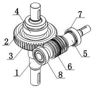
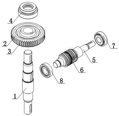
[0013] Such as figure 1 and figure 2 As shown, a worm transmission mechanism includes a transmission shaft 1 and a worm 5, the transmission shaft 1 is covered with a transmission gear 2, the outer surface of the transmission gear 2 is provided with tooth grooves 3, the outer surface of the worm 5 is provided with a thread groove 6, and the thread Groove 6 is docked with tooth groove 3, and thread groove 6 is connected with tooth groove 3 through occlusion; lock cap 4 is provided between transmission shaft 1 and transmission gear 2, and first lock ring 7 and second lock ring 7 are respectively provided at both ends of worm 5. lock ring 8.

[00...


PUM


Abstract

The invention discloses a worm transmission mechanism. The worm transmission mechanism comprises a transmission shaft and a worm. A transmission gear sleeves the transmission shaft. The external surface of the transmission gear is provided with gear slots. The external surface of the worm is equipped with threaded slots. The threaded slots are butt joint with the gear slots and engage with the gear slots. The worm is externally connected to a driving motor, and the rotation control over the worm is realized by the driving motor, so the transmission gear can move by means of the threaded slots and the gear slots and then the transmission shaft is controlled to rotate.

Description

technical field [0001] The invention relates to a transmission mechanism, in particular to a worm transmission mechanism. Background technique [0002] Worm drive is a kind of transmission that transmits motion and power between two axes that are interlaced in space. The angle between the two axes can be any value, and the commonly used one is 90°. Worm drives are used to transmit motion and power between staggered shafts. The existing worm transmission mechanism has poor stability during rotation. Contents of the invention [0003] The present invention mainly solves the technical problems existing in the prior art, thereby providing an external drive motor for the worm, through which the rotation of the worm can be controlled by the drive motor, so that the transmission gear can be moved conveniently through the thread groove and the tooth groove, and the transmission shaft can be controlled Rotating worm drive. [0004] Above-mentioned technical problem of the presen...

Claims


Application Information

Patent Timeline
Patent Type & Authority Applications(China)
IPC IPC(8): H02K7/116F16H1/16
Inventor 王琳
Owner 王琳
Why Eureka
Try Eureka