

Piston ring cutting-assisting positioning mechanism
A technology of auxiliary positioning and piston ring, applied in positioning device, clamping, supporting and other directions, can solve the problems of inaccurate judgment of cutting point and affect product quality, and achieve the effect of simple structure, convenient operation and convenient cutting
Inactive Publication Date: 2012-05-23
仪征双环设备制造有限公司
View PDF0 Cites 1 Cited by
- Summary
- Abstract
- Description
- Claims
- Application Information
AI Technical Summary
Problems solved by technology
[0002] When the current piston ring manufacturers cut the coiled piston rings into individual piston rings, most of them use manual cutting, that is, manual operation of the cutter for cutting operations. This method needs to be operated by people with sufficient work experience. People's experience judgment is not accurate enough, which affects product quality
Method used
View moreImage
Smart ImageViewing Examples

Examples
Embodiment Construction
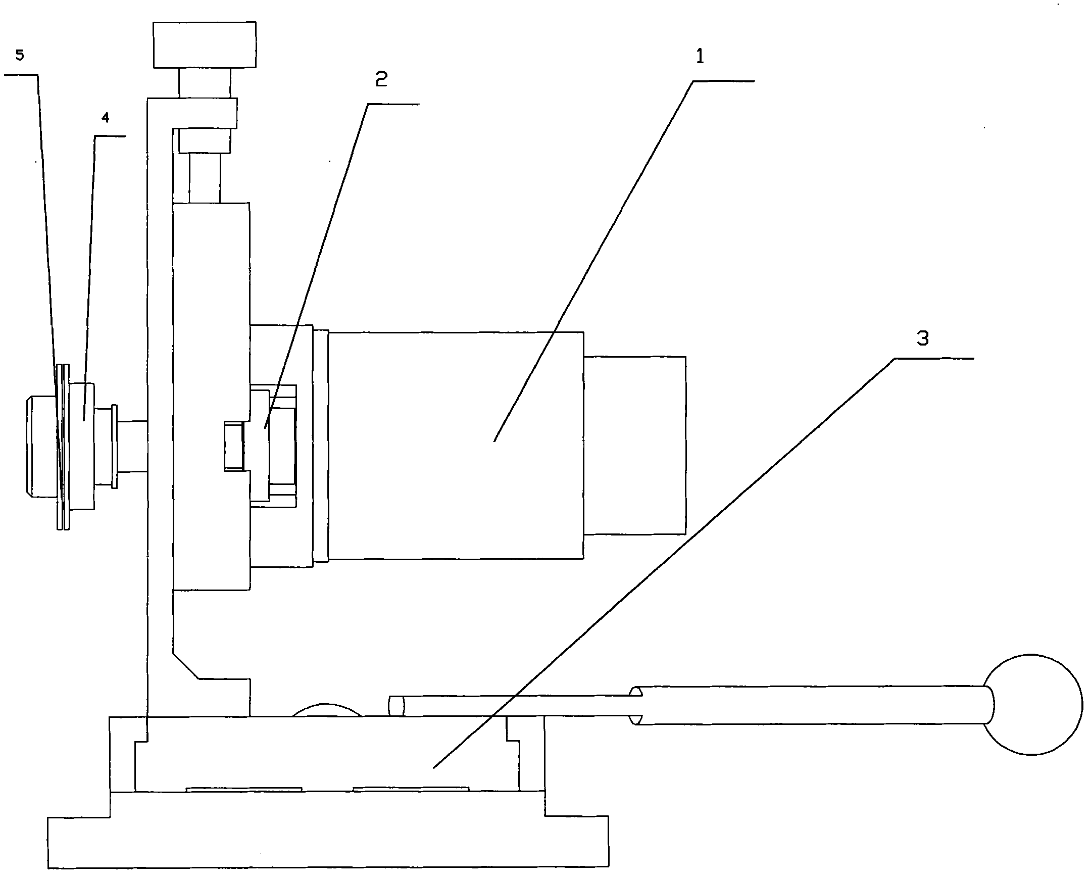
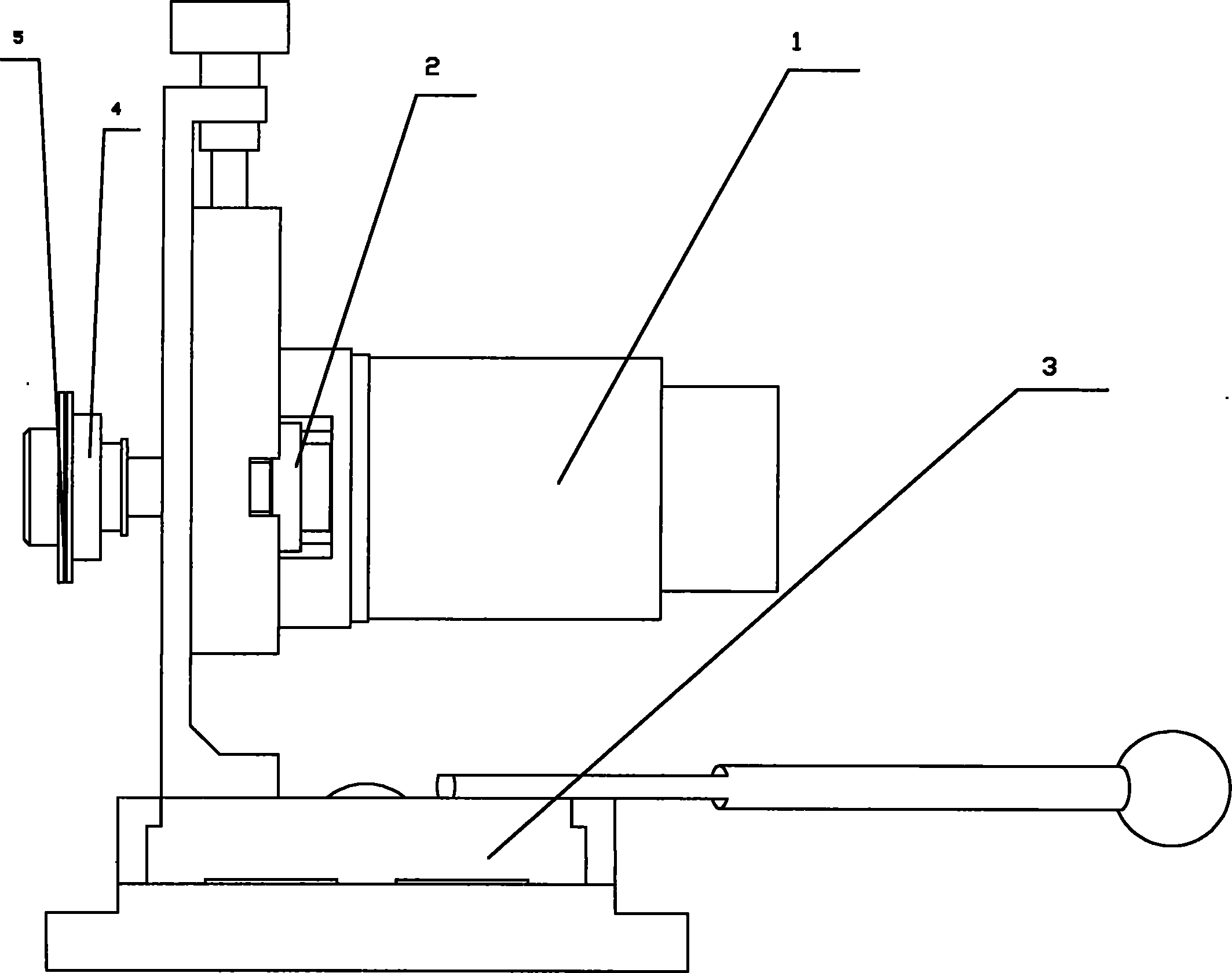
[0008] An auxiliary positioning device for piston ring cutting, comprising a stepping motor 1, a rotary bearing 2, and a frame 3, the rotary bearing 2 is connected to the output shaft of the stepping motor 1, and a pair of chucks 4 are provided at the front end of the rotary bearing 2 , There is a tooth groove 5 in the middle of the chuck 4, and an angle counter is connected to the rotating bearing 2.
Login to View More PUM
 Abstract
The invention relates to a piston ring cutting-assisting positioning mechanism, which comprises a step motor, a swivel bearing and a rack, the swivel bearing is connected with the output shaft of the step motor, a pair of chucks are arranged on the front end of the swivel bearing, tooth sockets are arranged between the chucks, and the swivel bearing is connected with an angle counter. The teeth of an uncut piston ring are engaged with the tooth sockets on the swivel bearing, the step motor is utilized to drive the swivel bearing to rotate, so that the tooth sockets are driven to rotate to drive the piston ring to rotate, and the angle counter connected with the swivel bearing can accurately control the rotation of the piston ring. The piston ring cutting-assisting positioning mechanism facilitates cutting, guarantees the accuracy of cutting, has a simple structure, and is convenient to operate.
Description
technical field [0001] The invention relates to an auxiliary positioning device for piston ring cutting. Background technique [0002] When the current piston ring manufacturers cut the coiled piston rings into individual piston rings, most of them use manual cutting, that is, manually operate the cutting knife for cutting operations. This method needs to be operated by people with sufficient work experience. People's experience and judgment are not accurate enough, which affects product quality. Contents of the invention [0003] In order to solve the above problems, the present invention provides a piston ring cutting auxiliary positioning device with accurate cutting and simple structure. [0004] The technical solution of the present invention is: comprising stepping motor, rotating bearing, frame, described rotating bearing is connected with the output shaft of stepping motor, and the front end of rotating bearing is provided with a pair of chuck, and the middle of c...
Claims
Login to View More Application Information
Patent Timeline
 Patent Type & AuthorityApplications(China)
IPC IPC(8): B23Q3/00B23Q7/00
Inventor丁少卫
Owner仪征双环设备制造有限公司