drive unit for vehicle
A driving device and wheel driving technology, which is applied in the direction of electric device, power device, electric power device, etc.
- Summary
- Abstract
- Description
- Claims
- Application Information
AI Technical Summary
Problems solved by technology
Method used
Image
Examples
no. 1 approach
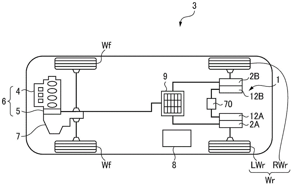
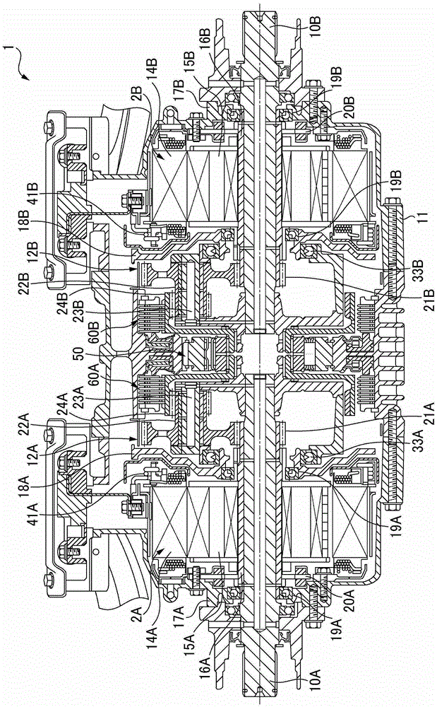
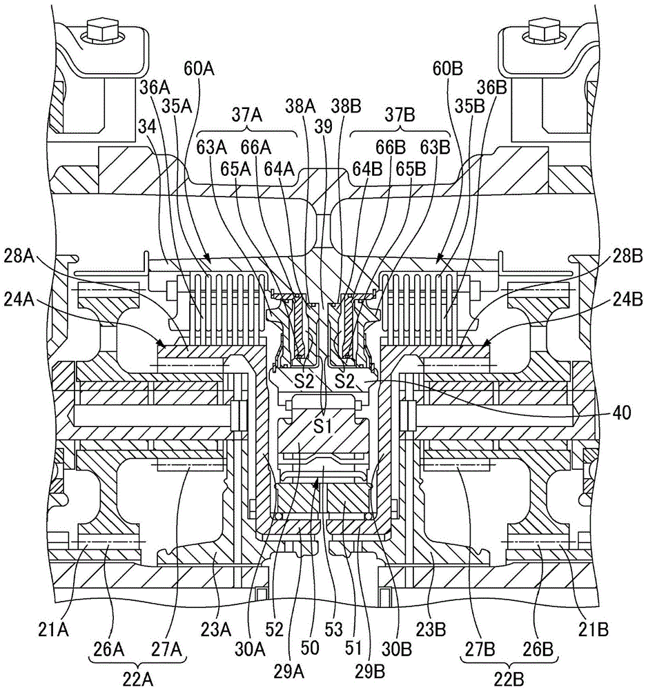
[0153] Figure 12 It is a speed collinear diagram of the rear-wheel drive device at the time of left-right reverse torque control (before the target rotation is reached) at high vehicle speed. In addition, in the figure, the vector which arises from the loss etc. which are stably applied to each rotating element mentioned above is abbreviate|omitted. When traveling at a high vehicle speed, as described above, the front-wheel drive is performed by the front-wheel drive device 6 , so the one-way clutch 50 is in a disengaged state. At this time, the hydraulic brakes 60A and 60B are controlled to be in a disengaged state. Therefore, the connected internal gears 24A and 24B are not locked and are in a rotating state.
[0154] In this state, torque control is performed so that the first electric motor 2A generates the first electric motor torque TM1 in the forward direction according to the target torque, and the second electric motor 2B generates the second electric motor torque ...
no. 2 approach
[0188] Next, the left-right reverse torque control of the second embodiment will be described.
[0189] The left-right reverse torque control of the present embodiment controls the first and second electric motors 2A and 2B so that the internal gears 24A and 24B become the target rotational speeds of the internal gears. In the following description, the following case will be described as an example. : In order to engage the hydraulic brakes 60A and 60B, a correction torque is added to the second electric motor 2B so that the internal gears 24A and 24B are in a zero rotation state (the rotation speed is zero) so that the rotation speed of the second electric motor 2B becomes the motor target rotation speed.
[0190] like Figure 9 As explained in , when the forward vehicle speed is high, the first and second electric motors 2A and 2B stop the power running drive, thereby acting from the axles 10A and 10B to the planetary carriers 23A and 23B in a forward direction for forward ...
no. 3 approach
[0212] Next, the left-right reverse torque control of the third embodiment will be described.
[0213] The left-right reverse torque control of the present embodiment controls the first and second electric motors 2A and 2B so that one of the planetary gears 22A and 22B becomes the target rotational speed of the planetary gear. In the following description, the following case is taken as an example To explain: in order to prevent backlash caused by the reversal of the rotation directions of the planetary gears 22A and 22B, the correction torque is applied to the first electric motor 2A so that the rotation directions of the planetary gears 22A and 22B are not reversed. control.
[0214] Figure 21 (a) is a speed collinear diagram of the rear-wheel drive device 1 during a left turn of the vehicle 3 , and the rear-wheel drive device 1 uses a first electric motor 2A to reverse the direction according to the target torque in order to assist the turning of the vehicle 3 . The torq...
PUM
 Abstract
Description
Claims
Application Information
 - R&D
- Intellectual Property
- Life Sciences
- Materials
- Tech Scout
- Unparalleled Data Quality
- Higher Quality Content
- 60% Fewer Hallucinations
Browse by: Latest US Patents, China's latest patents, Technical Efficacy Thesaurus, Application Domain, Technology Topic, Popular Technical Reports.
© 2025 PatSnap. All rights reserved.Legal|Privacy policy|Modern Slavery Act Transparency Statement|Sitemap|About US| Contact US: help@patsnap.com


