
Method and device for detecting icing at air inlet of turboshaft engine

A technology for engines and equipment, applied to the field of icing at the air intake, which can solve problems such as the difficulty of arranging ice sensors

Active Publication Date: 2016-02-10
EUROCOPTER
View PDF12 Cites 3 Cited by
  • Summary
  • Abstract
  • Description
  • Claims
  • Application Information

AI Technical Summary

Problems solved by technology

Rotors can be tilted from a hover flight position to a forward flight position, so arranging ice sensors can be difficult

Method used


Image

  • Method and device for detecting icing at air inlet of turboshaft engine
  • Method and device for detecting icing at air inlet of turboshaft engine

Examples


Embodiment Construction

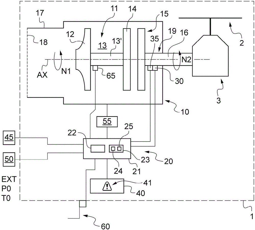
[0128] figure 1 An aircraft 1 of the invention is shown.

[0129] In particular, aircraft 1 includes lift and / or propulsion rotors 2 . The rotor 2 is driven in rotation by a power plant comprising at least one turboshaft engine 10 and at least one main gearbox 3 .

[0130] The engine 10 includes a gas generator 11 . The gas generator is conventionally provided with at least one compressor 12, a combustion chamber 13, and at least one expansion turbine 14 connected to the compressor 11 by a main shaft 13'.

[0131] figure 1 A single compressor 11 and a single expansion turbine 14 are shown. However, the number of compressors and expansion turbines can be optimized depending on requirements and does not limit the scope of the invention.

[0132] Furthermore, the compressor 11 , the expansion turbine 14 , and the main shaft 13 ′ mechanically linking them together begin to rotate together about the longitudinal axis AX of the engine. More precisely, the compressor 11, the ex...


PUM


Abstract

The invention relates to a method and device for detecting icing at an air inlet of a turboshaft engine, and relates to a method of detecting that the aircraft is flying in icing conditions. A processor unit determines a real power (Wr) developed by the turboshaft engine and a theoretical power (Wt) that the engine can develop in theory, the theoretical power (Wt) being determined using a theoretical model supplying a power by using at least of a speed of rotation of a gas generator of the engine. The processor unit determines a difference (epsilon) between the real power (Wr) and the theoretical power (Wt). The processor unit generates a warning to indicate the presence of icing conditions when the power difference (epsilon) is greater than a predetermined power threshold (SP) for a length of time longer than a time threshold (STPS), and when a temperature (T0) outside the aircraft lies between a low temperature threshold (SINF) and a high temperature threshold (SSUP).

Description

[0001] Cross References to Related Applications [0002] This application claims the benefit of FR1401738, filed July 29, 2014, the disclosure of which is hereby incorporated by reference in its entirety. technical field [0003] The invention relates to a method and a device for detecting icing at the air intake of a turboshaft engine. More specifically, the invention is in the field of systems for detecting icing of engines of aircraft. Background technique [0004] Aircraft, and more specifically rotorcraft, may encounter icing conditions while in flight. Thus, ice may accumulate on certain parts of the aircraft depending on atmospheric conditions. [0005] Rather, ice may become deposited on various components of the air intake. For example, an engine may have a grid protecting the air intake, which is at risk of ingesting ice in icy ambient conditions. [0006] Ice may tend to at least partially block the air intake. [0007] Ice can also become loose and can be in...

Claims


Application Information

Patent Timeline
Patent Type & Authority Applications(China)
IPC IPC(8): B64D15/20
CPCB64D15/20G08B19/02
Inventor R·罗斯奥托E·坎米
Owner EUROCOPTER
Features
  • Generate Ideas
  • Intellectual Property
  • Life Sciences
  • Materials
  • Tech Scout
  • Unparalleled Data Quality
  • Higher Quality Content
  • 60% Fewer Hallucinations
Learn More