
Icing detector

A technology for icing detectors and aircrafts, which is applied in the direction of instruments, measuring devices, deicing devices, etc. It can solve problems such as difficult assembly, difficult calibration, and complex structure of magnetostrictive vibrating cylinder-type icing detectors, reaching the size of the probe small, simple structure

Active Publication Date: 2012-01-11
COMAC +2
View PDF4 Cites 21 Cited by
  • Summary
  • Abstract
  • Description
  • Claims
  • Application Information

AI Technical Summary

Problems solved by technology

However, they also have certain defects: the magnetostrictive vibrating cylinder ice detector has complex structure, high production process requirements, difficult calibration, and cannot be installed flush and conformal on curved surfaces (such as the leading edge of aircraft wing tail); Although the electro-diaphragm ice detector is small in size and weight, it can achieve flush and conformal installation on curved surfaces to a certain extent, but the production requirements for its sensitive materials are stricter, the process is more complicated, and the assembly is more difficult

Method used


Image

  • Icing detector
  • Icing detector
  • Icing detector

Examples


Embodiment Construction

[0030] Preferred embodiments of the present invention will be described in detail below with reference to the accompanying drawings.

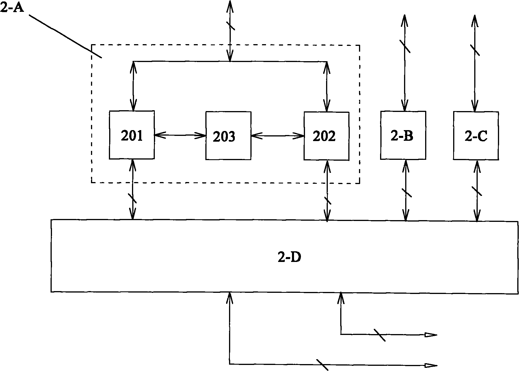
[0031] The image icing detector according to the first preferred embodiment of the present invention mainly includes an image acquisition system and an image processing system, the former is used to acquire images from the surface of an object, and then the latter calculates and analyzes the acquired surface images, so that the final Obtain the icing condition on the surface of the object.

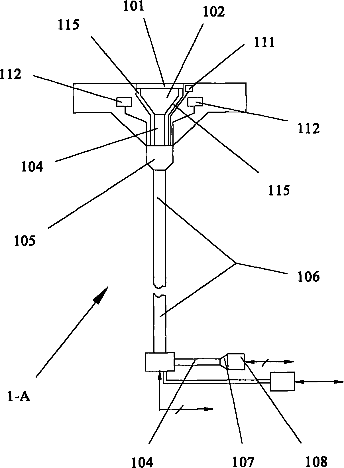
[0032] First refer to figure 1 , which shows the image acquisition system 1-A of the image icing detector according to the above-mentioned first preferred embodiment.

[0033] Among them, the core component of the image acquisition system 1-A is the image transmission fiber optic bundle 104, which can receive the surface image of the object at the front end, and transmit the surface image to other components connected to the rear end along the optical fibe...


PUM


Abstract

The invention discloses an image icing detector, which comprises an image acquiring system (1-A) and an image processing system (2-A), wherein the image acquiring system (1-A) can be used for acquiring an image of an object surface; the image processing system (2-A) can be used for analyzing the image so as to acquire the icing condition of the object surface; and the image acquiring system (1-A) comprises an image transmitting optical fiber bundle (104). By the detector, application requirements under a special spatial requirement can be met without the miniaturization design of the image acquiring system (1-A).

Description

technical field [0001] The invention relates to an icing detection device, which is used for detecting the icing condition on the surface of an object, so as to obtain information such as whether it is icing, the type of icing, the thickness and area of ​​icing, and the like. Background technique [0002] In many cases, it is necessary to detect and analyze the icing condition of a specific surface or part of an object. For example, in cold regions, it is necessary to monitor the icing condition of the road surface in winter, to detect the icing condition of the blades of the wind turbine and some rotating parts, and to monitor the multiple parts of the body (such as the windshield) during the flight of the aircraft. , wing tail leading edge, engine intake, etc.) to monitor the icing phenomenon to avoid adverse effects of icing on flight and prevent serious flight safety accidents caused by icing. It should be noted that the word "ice" mentioned in this application shall in...

Claims


Application Information

Patent Timeline
IPC IPC(8): G01B11/00G01B11/06G01B11/28G01V8/10B64D15/20
CPCB64D15/20G06T2207/30156B64D15/00G06T7/0004G02B6/06
Inventor 陈迎春叶林张淼葛俊峰冯丽娟刘铁军周峰
Owner COMAC
Learn More