Power cable tensioning device

A technology for power cables and tensioning devices, which is applied in the directions of transportation and packaging, transportation of filamentous materials, and processing of thin materials, etc., can solve the problems of increased length of transmission cables, inconvenient use, and unfavorable ground lightning weather.

Inactive Publication Date: 2016-02-10
STATE GRID CORP OF CHINA +1
View PDF5 Cites 0 Cited by
  • Summary
  • Abstract
  • Description
  • Claims
  • Application Information

AI Technical Summary

Problems solved by technology

[0002] During the transmission of electric energy in the cable, especially in the long-term transmission process, the cable is prone to bending and falling under its own gravity; on the one hand, the length of the transmission cable will i

Method used


Image

  • Power cable tensioning device
  • Power cable tensioning device
  • Power cable tensioning device

Examples


Embodiment Construction

[0020] based on the following Figure 1-7 An embodiment of the present invention is described.

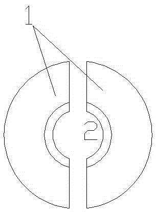
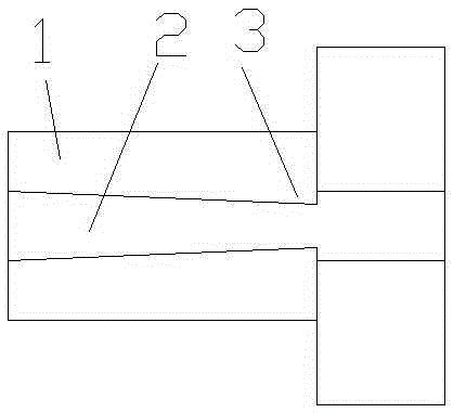
[0021] A power cable tensioning device includes a clamping hoop 1 composed of two halves of clamping units, and the clamping hoop is internally arranged in a channel 2 for cables to pass through.

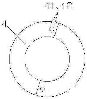
[0022] The inner side of the clamp channel 2 is provided with a boss 3 for clamping the power cable; the outside of the clamp 1 is provided with an external thread, and a clamp nut 4 is provided in cooperation with the outer wall of the clamp. The nut 4 is composed of two half-rings, wherein each side of the half-ring is respectively provided with a protruding head 41 and a groove 42, and the protruding head fits into the groove.

[0023] A hanging hole is provided on the outside of each half ring, and a pull rope 5 is correspondingly provided on the hanging hole; a support 6 is also included, and the bottom of the support 6 is hinged on the base 7, and the upper end both sides of the s...


PUM


Abstract

A power cable tensioning device comprises a clamping hoop. An external thread is arranged on the outer side of the clamping hoop, and a clamping nut is arranged in cooperation with the outer wall of the clamping hoop. The clamping nut is composed of two semi-rings, wherein the side of each semi-ring is provided with a convex head and a concave groove, and the convex heads are matched with the concave grooves. A hanging hole is formed in the outer side of each semi-ring, and a traction rope is arranged in each hanging hole correspondingly. The power cable tensioning device further comprises a support. The lower side of the support is hinged to a base. The two sides of the upper end of the support are each provided with a hanging ring. Each hanging ring comprises an upper roller and a lower roller. Stop rods are arranged on the two sides of each lower roller. The traction ropes wind across the upper rollers and the lower rollers and then are provided with a tray. Cylindrical pressing blocks are borne on the tray. A through groove is formed in each pressing block in the radial direction of the pressing block. Each pressing block is provided with a bent groove. The tail end of each bent groove is communicated with the tail end of the inner side of the corresponding through groove. A telescopic device is arranged on the base, one end of the telescopic device is fixed on the base, and the other end of the telescopic device is hinged to the support.

Description

technical field [0001] The invention relates to a power cable tensioning device. Background technique [0002] During the transmission of electric energy in the cable, especially in the long-term transmission process, the cable is prone to bending and falling under its own gravity; on the one hand, the length of the transmission cable will increase, and on the other hand, it will also form The arc electric field is not conducive to the ground and lightning weather. [0003] The existing tensioning devices are relatively complicated, inconvenient to use and not effective in tensioning. Contents of the invention [0004] The object of the present invention is to overcome the disadvantages of the prior art and provide a power cable tensioning device, which has the advantages of simple structure and good tensioning effect compared with the prior art. [0005] In order to solve the problems of the technologies described above, the technical solution of the present invention i...

Claims


Application Information

Patent Timeline
IPC IPC(8): B65H59/10
Inventor 亓振新亓勇刘晓艳许强张斌吕胜军陈兴连许少健张海霞吕金亮潘佳毕安宁朱晓阳崔东海边金龙李祥莹徐继凯郝强朱伟波董梅陈敬娟王慧张玉倩王鹏邹悦
Owner STATE GRID CORP OF CHINA
Why Eureka
Try Eureka