Mobile automatic bait feeding machine and feeding method

A technology of automatic feeding and feeding method, applied in fish farming, application, climate change adaptation and other directions, can solve the problems of uneven growth of fish, reduced economic benefits, uneven bait, etc., and achieve uniform feeding method and economic benefits. High, low resistance effect

Inactive Publication Date: 2018-06-01
HEILONGJIANG RIVER FISHERY RES INST CHINESE ACADEMY OF FISHERIES SCI
View PDF10 Cites 0 Cited by
  • Summary
  • Abstract
  • Description
  • Claims
  • Application Information

AI Technical Summary

Problems solved by technology

[0002]Now, most of the freshwater fish are fed by small boats along the breeding area and fed manually. The cast is uneven, some fish with good physical strength grab more bait and grow fast, while some fish with poor physical strength eat less bait and grow small, which makes the growth of fish uneven, affecting the quality and reducing the quality of fish. economic benefits

Method used


Image

  • Mobile automatic bait feeding machine and feeding method
  • Mobile automatic bait feeding machine and feeding method

Examples


Embodiment 1

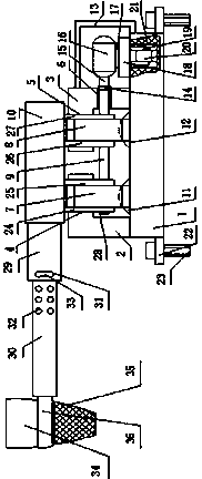
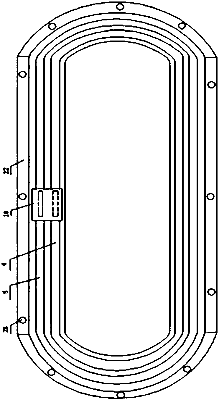
[0021] A mobile automatic bait throwing machine, which consists of: a fish pond, an annular slideway is laid on the ground around the fishpond, and the annular slideway includes a bottom plate 1, and the inner side of the bottom plate is connected to the left L Shaped limiting ring 2, the outside of the base plate is connected to the right L-shaped limiting ring 3, the top of the left L-shaped limiting ring has a left circular wheel slideway 4, the right L-shaped limiting ring There is a right circular wheel slideway 5 at the top, and a shaft slideway 6 is provided on the outer side of the right L-shaped limit ring. The left circular wheel 7 is inserted into the left circular wheel slideway, and the left circular wheel 7 is inserted into the right circular wheel slideway. The right round wheel 8, the left round wheel and the right round wheel are connected by a rotating shaft 9, the rotating shaft is connected to the support plate, the support plate is connected to the sliding ...

Embodiment 2

[0023] In the mobile automatic bait feeding machine described in Embodiment 1, the rotating shaft is connected to the coupling 14, the coupling is connected to the motor output shaft 15, the motor output shaft is connected to the motor 16, and the motor is connected to Support frame 17, described support frame connects support slide plate 18, and described support slide plate connects connection support plate 19, and described connection support plate connects moving wheel 20, and described rotating shaft stretches out described shaft slideway, and The described motor is connected to the power supply and the control switch.

Embodiment 3

[0025] In the mobile automatic bait feeding machine described in Embodiment 2, a vertical ring-shaped chute 21 is opened on the outside of the bottom plate, and the moving wheel is installed in the vertical ring-shaped chute, and the moving wheel moves along the The above-mentioned vertical annular chute slides, the bottom plate is connected to the extension plate 22, and the extension plate is fixed on the ground by expansion bolts 23.


PUM


Abstract

Provided are a mobile automatic feeder and a feeding method. The mobile automatic feeder comprises a pond, and the mobile automatic feeder is characterized in that an annular sliding track is laid on ground on the periphery of the pond, the annular sliding track comprises a base plate, the inner side of the base plate is connected with a left L-shaped spacing ring, and the outer side of the base plate is connected with a right L-shaped spacing ring. The top of the left L-shaped spacing ring is provided with a left round wheel slide, and the top of the right L-shaped spacing ring is provided with a right round wheel slide. The outer side edge of the right L-shaped spacing ring is provided with a shaft slide. A left round wheel is inserted in the left round wheel slide. A right round wheel is inserted in the right round wheel slide. The left round wheel and the right round wheel are connected through a rotating shaft. The rotating shaft is connected with a support plate. The support plate is connected with a sliding block. The sliding block is connected with a telescopic boom. The telescopic boom is connected with a bait dispenser. The base plate is connected with a group of left vibrator points and a group of right vibrator points. The mobile automatic feeder is used to feed fishes.

Description

technical field [0001] The invention relates to a mobile automatic bait feeding machine and a feeding method. Background technique [0002] Nowadays, most of the freshwater fish feedings are fed by small boats along the breeding area manually. Many of the feds are piled up and dropped, and the feds are not distributed evenly. If there are many, they will grow fast, and some fish with poor physical strength will eat less bait and grow small, making the growth of fish uneven, affecting quality and reducing economic benefits. Contents of the invention [0003] The purpose of the present invention is to provide a mobile automatic bait feeding machine and a feeding method that can evenly put in bait, and the put in bait is evenly laid on the water surface, which improves the quality of fish breeding. [0004] Above-mentioned purpose realizes by following technical scheme: [0005] A mobile automatic bait throwing machine, which consists of: a fish pond, an annular slideway is...

Claims


Application Information

Patent Timeline
Patent Type & Authority Patents(China)
IPC IPC(8): A01K61/80
CPCY02A40/81
Inventor 覃东立姜海峰高磊康凯陈中祥
Owner HEILONGJIANG RIVER FISHERY RES INST CHINESE ACADEMY OF FISHERIES SCI
Why Eureka
Try Eureka