artificial power network

A technology of artificial power network and AC power grid, applied in the direction of measuring electricity, measuring electrical variables, instruments, etc., can solve the problems of long time consumption, increased test cost, impedance offset of power supply network, etc., to ensure performance characteristics and assist rectification analysis Effect

Active Publication Date: 2018-10-23
DELTA ELECTRONICS JIANGSU
View PDF11 Cites 0 Cited by
  • Summary
  • Abstract
  • Description
  • Claims
  • Application Information

AI Technical Summary

Problems solved by technology

[0003] At present, there are mainly three methods for the rectification and analysis of conducted interference. The first method is the empirical method. The designer formulates some countermeasures for the product based on the past experience in solving the conducted interference problem, and tries, measures, tries again, and measures again. To solve the problem of conducted interference, this method has the advantages of cost-effectiveness, but it takes a long time in many cases and completely depends on the experience of the designer; the second method: with the help of the filter method, the designer adds a filter to the product, and then measures Observing the improvement situation, this method has the advantages of easy implementation and low device cost, but the filtering characteristics of the filter are usually obtained under the 50Ω measurement system, and the impedance of different products is different, and in many cases, adding a filter cannot be expected improvement; the third method: use common-differential mode separation equipment, which has mature common-mode-differential mode separation equipment on the market, and can quantify the measurement data. Designers can obtain the interference type according to the measurement results, and then according to the interference type ( However, the implementation of this scheme requires two artificial power networks (AMN), which increases the test cost. At the same time, the use of common-differential mode separation equipment may cause the overall impedance of the power network to shift. cause measurement error

Method used


Image

  • artificial power network
  • artificial power network
  • artificial power network

Examples


Embodiment Construction

[0020] Embodiments of the present invention will be described below with reference to the drawings. Elements and features described in one drawing or one embodiment of the present invention may be combined with elements and features shown in one or more other drawings or embodiments. It should be noted that representation and description of components and processes that are not related to the present invention and known to those of ordinary skill in the art are omitted from the drawings and descriptions for the purpose of clarity.

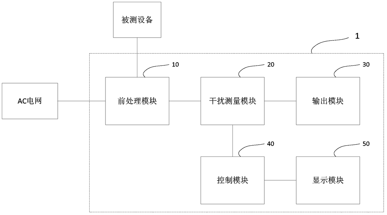
[0021] see figure 1 Shown is a structural diagram of an artificial power supply network 1 according to an embodiment of the present invention.

[0022] In this embodiment, the artificial power supply network 1 includes, for example, a pre-processing module 10 , an interference measurement module 20 , an output module 30 , a control module 40 and a display module 50 . in addition, figure 1 Also shown is the external AC grid and the equipment unde...


PUM


Abstract

The invention relates to an artificial mains network. In one embodiment of the invention, the artificial mains network comprises an interference measuring module for receiving interference signals of a tested device and outputting different interference measuring signals according to different measuring modes for measurement of a measuring device; and a control module for controlling the measuring mode of the interference measuring module. For instance, the measuring mode of the interference measuring module can comprise L-line interference measurement, N-line interference measurement, differential mode interference measurement and common-mode interference measurement. According to the invention, the artificial mains network has a common and differential mode interference separating function, can ensure the performance feature of the artificial mains network, guarantees the reliability of a conducted interference measurement result and can also provide an interference type for design personnel during correction and analysis of conducted interference for assistance of the correction and analysis.

Description

technical field [0001] The present invention generally relates to an artificial power network, and more specifically relates to an artificial power network with a common-differential mode separation function. Background technique [0002] With the advancement of modern technology, the demand for electronic products is becoming more and more diverse. In order to ensure that multiple types of electronic products work together in the same environment, the problem of electromagnetic compatibility of electronic products is becoming more and more prominent. At present, most electronic products need to be certified for electromagnetic compatibility measurement before they go on the market. Conducted interference emission is the main measurement item of electromagnetic compatibility. When measuring the conducted interference emission of electronic products, it is often encountered that the emission value exceeds the corresponding specified limit value. In this case, the designer n...

Claims


Application Information

Patent Timeline
Patent Type & Authority Patents(China)
IPC IPC(8): G01R31/00
Inventor 李柏霖汪丽萍万正堂
Owner DELTA ELECTRONICS JIANGSU
Why Eureka
Try Eureka