Steel ladle transferring device

A transfer device and ladle technology, which is applied in the direction of casting molten material containers, metal processing equipment, casting equipment, etc., can solve the problems of high safety requirements, low safety, and high dependence on the level of crane operators, and achieve high safety , easy operation and simple structure

Inactive Publication Date: 2016-02-24
广西长城机械股份有限公司
View PDF7 Cites 1 Cited by
  • Summary
  • Abstract
  • Description
  • Claims
  • Application Information

AI Technical Summary

Problems solved by technology

However, this pouring method is less safe to transfer the ladle by crane, and it is highly dependent on the level of the crane operator, and has higher requirements on the reliability and safety of the equipment.

Method used


Image

  • Steel ladle transferring device
  • Steel ladle transferring device

Examples


Embodiment Construction

[0016] The specific embodiments of the present invention will be described in detail below in conjunction with the accompanying drawings, but it should be understood that the protection scope of the present invention is not limited by the specific embodiments.

[0017] Unless expressly stated otherwise, throughout the specification and claims, the term "comprise" or variations thereof such as "includes" or "includes" and the like will be understood to include the stated elements or constituents, and not Other elements or other components are not excluded.

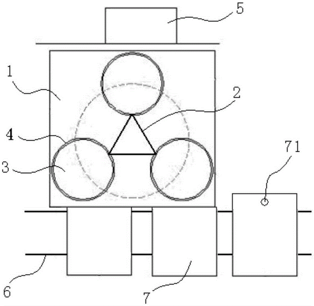
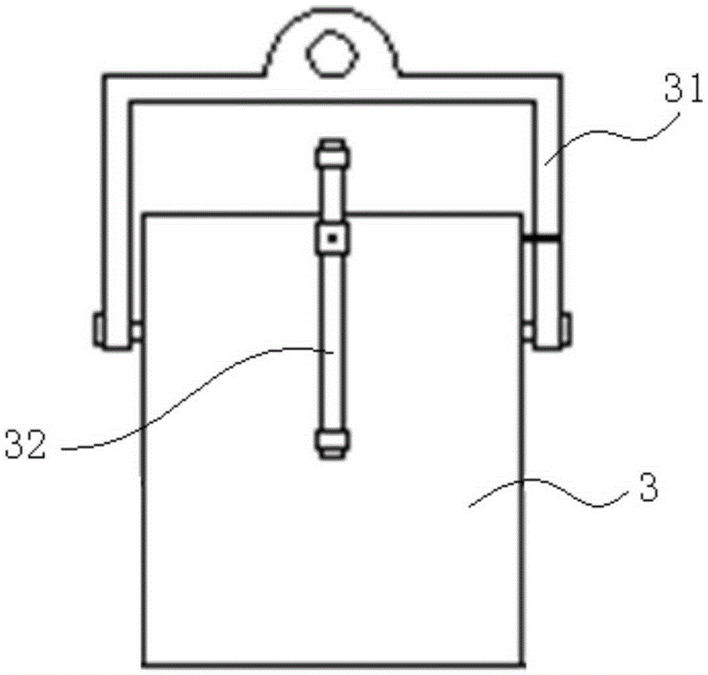
[0018] Such as Figure 1 to Figure 2 As shown, an embodiment according to the specific implementation mode of the present invention is: a ladle transfer device, such as figure 1 As shown, it includes a base 1, a multi-angle turntable 2 and a ladle 3, the base 1 is arranged between the hearth 5 and the sand conveyor belt 6, and the side corresponding to the base 1 and the sand conveyor belt 6 is located above the sand conve...


PUM


Abstract

The invention discloses a steel ladle transferring device. The steel ladle transferring device comprises: a base arranged between a furnace platform and a sand mold conveyor belt, wherein one side, corresponding to the sand mold conveyor belt, of the base is located above the sand mold conveyor belt; a polygonal rotary table arranged on the base in a rotatable manner and driven by a rotating mechanism to rotate; and steel ladles, wherein one steel ladle is fixedly arranged at each angle of the polygonal rotary table; a water outlet is formed in a lower end of each steel ladle, and when the steel ladle rotates to be above the sand mold conveyor belt through the polygonal rotary table, the water outlet of the steel ladle is located directly above a pouring gate of a sand mold. The steel ladle transferring device is capable of circularly changing the position of the steel ladle at each angle through the polygonal rotary table, so that the steel ladle can be transferred conveniently, and adding steel liquid to the steel ladle and pouring can be circularly carried out; the steel ladle transferring device is simple in structure, very convenient to operate, relatively low in cost and high in safety.

Description

technical field [0001] The invention relates to the field of casting, in particular to a ladle transfer device. Background technique [0002] In the casting process of castings, the smelted molten steel is usually poured from the melting furnace to the ladle, and then the ladle is transferred to the top of the sand mold to be poured, and the molten steel is poured or bottom poured into the prepared sand mold. In some foundry enterprises, the molten steel is transferred to a small ladle, and the pouring is completed by manually lifting the ladle. Most enterprises use the crane to lift the ladle, receive the molten steel in front of the melting furnace, then place the ladle in the automatic pouring machine by the crane, the conveyor belt under the automatic pouring machine transports the sand mold to the bottom of the ladle, and the automatic pouring machine completes the pouring. However, this pouring method is less safe to transfer the ladle by a crane, and it is highly de...

Claims


Application Information

Patent Timeline
Patent Type & Authority Applications(China)
IPC IPC(8): B22D41/13
CPCB22D41/13
Inventor 田辉黎石汉廖钊钟昌延黄正富莫九生
Owner 广西长城机械股份有限公司
Why Eureka
Try Eureka