
A Straight Edge Constraint Device for Variable Angle Curved Plates

A technology of restraint device and curved plate, which is applied in the direction of measuring device, strength characteristics, machine/structural component testing, etc., can solve the problem that the normal direction of the curved plate test piece is not the actual one, and achieve simple structure and convenient installation Effect

Active Publication Date: 2018-10-09
CHINA AIRPLANT STRENGTH RES INST
View PDF8 Cites 1 Cited by
  • Summary
  • Abstract
  • Description
  • Claims
  • Application Information

AI Technical Summary

Problems solved by technology

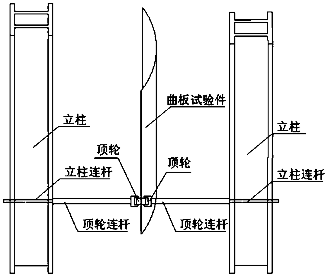
The top wheel device has two disadvantages. First, since the column is fixed, the top wheel device can only extend in a 90-degree direction along the side of the column, so the constraint angle of the top wheel is not the actual curved plate test piece method. Second, because the direction of the top wheel is not along the normal direction of the curved plate test piece, and the width of the roller cannot be completely pressed against the straight edge, so the roller of the top wheel should be turned 90 degrees, so that the roller is in the direction of the test piece. When pulling / compressing axially, there will be friction on the rollers

Method used


Image

  • A Straight Edge Constraint Device for Variable Angle Curved Plates
  • A Straight Edge Constraint Device for Variable Angle Curved Plates
  • A Straight Edge Constraint Device for Variable Angle Curved Plates

Examples


Embodiment Construction

[0028] In order to make the objectives, technical solutions and advantages of the present invention clearer, the technical solutions in the embodiments of the present invention will be described in more detail below in conjunction with the drawings in the embodiments of the present invention. In the drawings, the same or similar reference numerals denote the same or similar elements or elements having the same or similar functions throughout. The described embodiments are some, but not all, embodiments of the invention. The embodiments described below by referring to the figures are exemplary and are intended to explain the present invention and should not be construed as limiting the present invention. Based on the embodiments of the present invention, all other embodiments obtained by persons of ordinary skill in the art without creative efforts fall within the protection scope of the present invention. Embodiments of the present invention will be described in detail below ...


PUM


Abstract

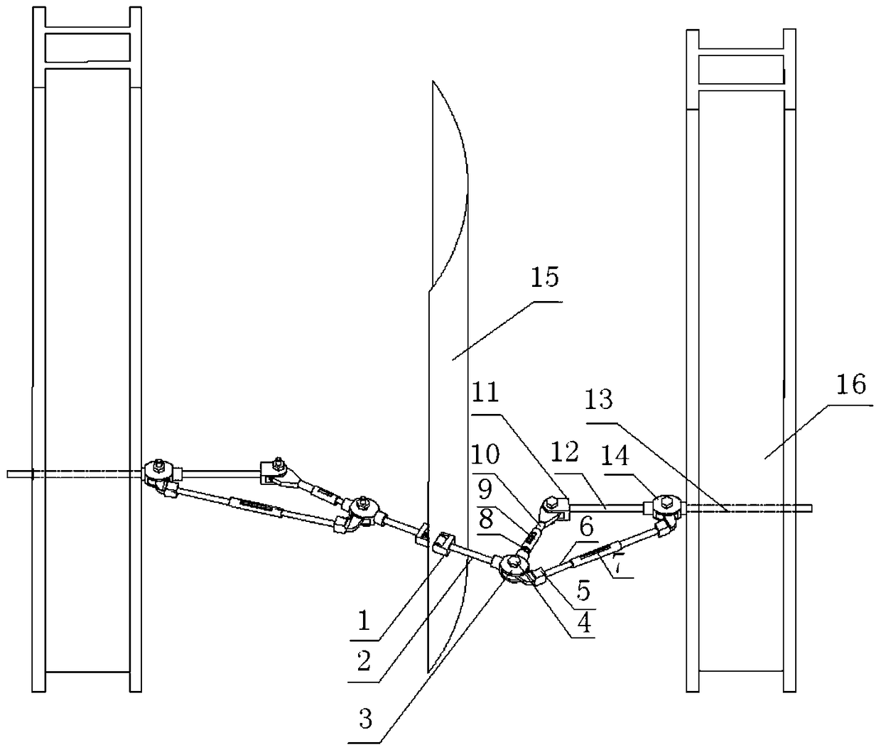
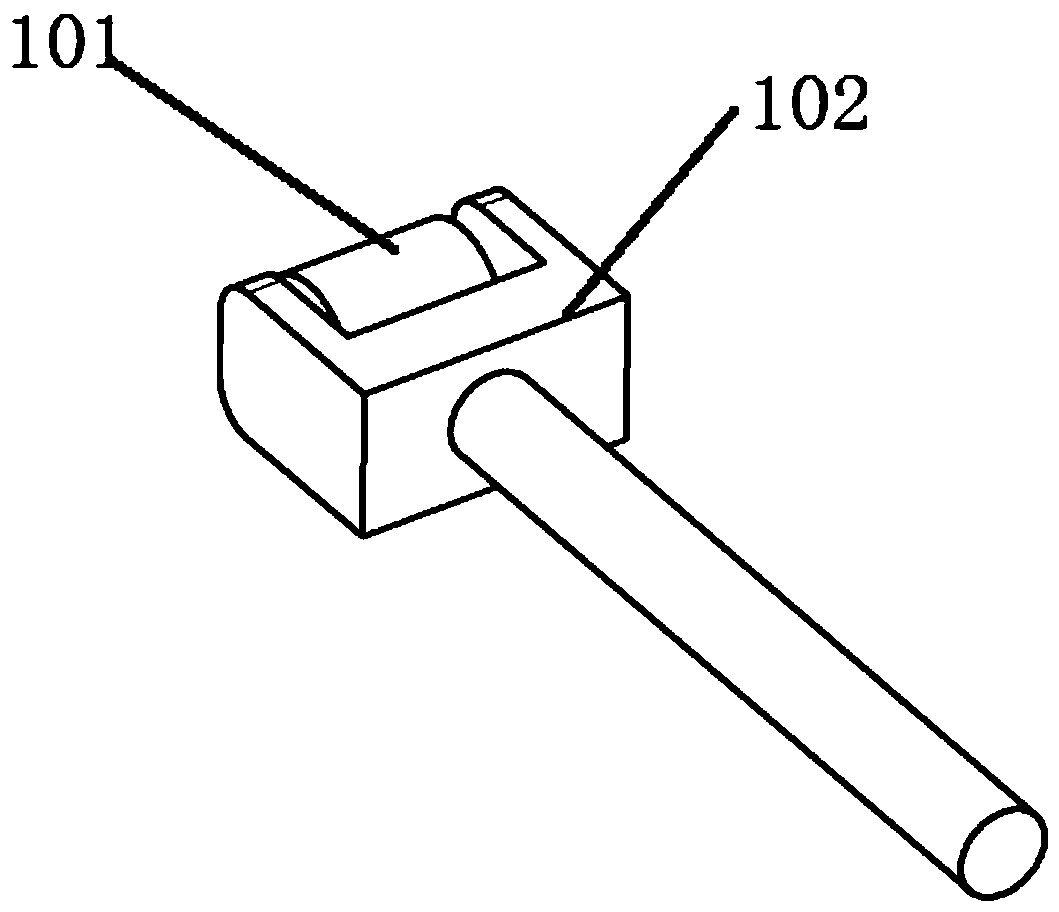
The invention discloses a variable-angle curved plate straight edge constraint device and belongs to the field of an airplane strength test. The device comprises a top wheel and a triangular adjustable mechanism for adjusting the top wheel, one end of the top wheel is provided with a rolling wheel (101), and the top wheel contacts a curved plate test piece through the rolling wheel (101); and, in the triangular adjustable mechanism, the first vertex of the triangular adjustable mechanism is connected with the other end of the top wheel (1), the second vertex is connected with a column, the third vertex is a hinge point, a hypotenuse connecting rod (6) is hinged between the first vertex and the second vertex, the length of the hypotenuse connecting rod (6) is adjustable, and a leg connecting rod (8) the length of which is adjustable is disposed between the first vertex and the third vertex. Through adjustments of lengths of the connecting rods of the triangular adjustable mechanism, directions of constraints of the top wheel are directions of the normal lines of legs of the curved plate test piece, constraint conditions of the legs of an airplane curved plate can be accurately simulated, and load requirements of curved plates in different curvatures are met; and the device has the advantages of simple installation and high universality.

Description

technical field [0001] The invention belongs to the field of aircraft strength tests, and in particular relates to a straight-edge constraint device for a variable-angle curved plate. Background technique [0002] In the aircraft structural strength test, especially the fatigue test of the fuselage curved plate, when the axial tension / compression load is applied, the straight edge in the circumferential direction should be constrained. By constraining the normal direction of the curved plate, the axial Orientation is not constrained. [0003] At the current stage, the device that realizes the restraint of the straight edge of the curved plate is usually the top wheel device, such as figure 1 As shown, firstly, the column connecting rod is fixed to the column by bolts, then the top wheel connecting rod is connected to the column connecting rod through a screw sleeve, and finally the top wheel and the top wheel connecting rod are connected through threaded holes, so as to con...

Claims


Application Information

Patent Timeline
Patent Type & Authority Patents(China)
IPC IPC(8): G01M13/00G01N3/02
CPCG01M13/00G01N3/02
Inventor 张侃陈安廖江海臧伟峰
Owner CHINA AIRPLANT STRENGTH RES INST
Learn More