
Detection device of offshore platform hydraulic type elevating mechanism

A lifting mechanism and offshore platform technology, applied in the field of offshore platform lifting system testing, can solve the problems of difficult to meet accurate detection standards, low accuracy of ocean simulation, unstable detection accuracy, etc., to reduce detection cost, reduce detection difficulty, The effect of structural stability

Active Publication Date: 2017-05-17
KEEN OFFSHORE ENG CO LTD
View PDF6 Cites 0 Cited by
  • Summary
  • Abstract
  • Description
  • Claims
  • Application Information

AI Technical Summary

Problems solved by technology

[0003] Due to the complex and changeable offshore environment, offshore operating platforms are subject to wind currents, ocean current impacts, and ups and downs at any time. Therefore, before installing the hydraulic continuous lifting mechanism of the offshore platform on the offshore lifting platform, a simulation test is required to test the various performances of the lifting device. However, the simulation test equipment currently used for the lifting mechanism of offshore platforms only detects the maximum load value that the lifting mechanism can output. Compared with the actuality of the ocean simulation, there are still some performances that are difficult to meet the accurate detection standards. , the error rate is high, and the current simulation test equipment has a complex structure, low detection efficiency, high detection difficulty, high detection cost and unstable detection accuracy

Method used


Image

  • Detection device of offshore platform hydraulic type elevating mechanism
  • Detection device of offshore platform hydraulic type elevating mechanism
  • Detection device of offshore platform hydraulic type elevating mechanism

Examples


Embodiment Construction

[0029] The technical solutions of the present invention will be further described below in conjunction with the accompanying drawings and through specific implementation methods.

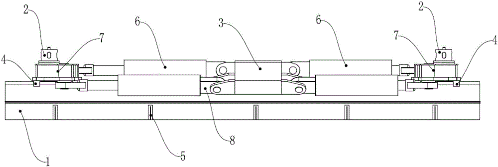
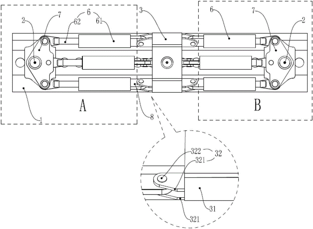
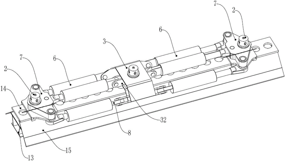
[0030] like figure 1 As shown, a detection device for a hydraulic lifting mechanism of an offshore platform includes a base 1, two lifting mechanisms to be tested and a connection box 3; the connection box 3 is arranged on the base 1 through a guide slide 4, And the base 1 is divided into a left lifting mechanism installation area A and a right lifting mechanism installation area B, such as figure 2 shown;

[0031] The left lifting mechanism installation area A and the right lifting mechanism installation area B are respectively equipped with two described lifting mechanisms to be tested, and the left lifting mechanism installation area A and the right lifting mechanism installation area B are all provided with a plurality of first pin holes 11. The base 1 is also provided with a second pin hole ...


PUM


Abstract

The invention provides a detection device of an offshore platform hydraulic type elevating mechanism. The detection device comprises a base, two to-be-detected elevating mechanisms and a connection box body. The connection box body separates the base into a left elevating mechanism installation region and a right elevating mechanism installation region. The two to-be-detected elevating mechanisms are installed on the left elevating mechanism installation region and the right elevating mechanism installation region respectively. Multiple first pin holes are arranged in each of the left elevating mechanism installation region and the right elevating mechanism installation region. A second pin hole arranged in the lower end of the connection box body is arranged in the base. Each to-be-detected elevating mechanism comprises a pin mechanism, multiple lifting oil cylinders and an elevating slide seat, wherein one end of the lifting oil cylinder drives the pin mechanism to go up and down through the elevating slide seat; and the pin of the pin mechanism is inserted into the corresponding first pin hole during detection. A locking pin which can be inserted into the second pin hole during detection is arranged on the connection box body. According to the invention, a load detection test of two to-be-detected elevating mechanisms can be achieved simultaneously, and the detection device is characterized by high detection efficiency, low detection difficulty, high precision and flexibility and quite simple structure.

Description

technical field [0001] The invention relates to the technical field of testing an offshore platform lifting system, in particular to a detection device for a hydraulic lifting mechanism of an offshore platform. Background technique [0002] The offshore platform lifting system is a key part of the self-elevating offshore operation platform. The lifting mechanism drives the legs of the platform to move up and down to realize the lifting of the offshore operation platform, that is, when the offshore operation platform reaches the operating position, the legs are lowered and the offshore The operation platform is lifted to the specified height on the sea surface and then ballasted, so that the legs are firmly positioned on the seabed; when the operation is completed and the voyage is completed, the offshore operation platform is lowered to the sea level, and the legs are pulled out, and the legs are always raised during the return process . [0003] Due to the complex and chan...

Claims


Application Information

Patent Timeline
IPC IPC(8): G01M99/00
CPCG01M99/007
Inventor 吴平平刘会涛李光远陆军张静波马振军
Owner KEEN OFFSHORE ENG CO LTD
Learn More