High efficiency FIR filter cascade DFT algorithm

A filter stage and filter technology, which is applied in the direction of instruments, measuring devices, spectrum analysis, etc., can solve problems such as large amount of calculation, poor practicability, and very large hardware requirements, and achieve the effect of solving large amount of calculation and improving calculation efficiency

Active Publication Date: 2016-02-24
XUJI GRP +3
View PDF5 Cites 2 Cited by
  • Summary
  • Abstract
  • Description
  • Claims
  • Application Information

AI Technical Summary

Problems solved by technology

The actual test shows that the hardware requirements are very large and the practicability is very poor
For a 120th-order FIR filter, if the 80-point DFT algorithm is cascaded, only 121*80 floating

Method used


Image

  • High efficiency FIR filter cascade DFT algorithm
  • High efficiency FIR filter cascade DFT algorithm
  • High efficiency FIR filter cascade DFT algorithm

Examples


Embodiment Construction

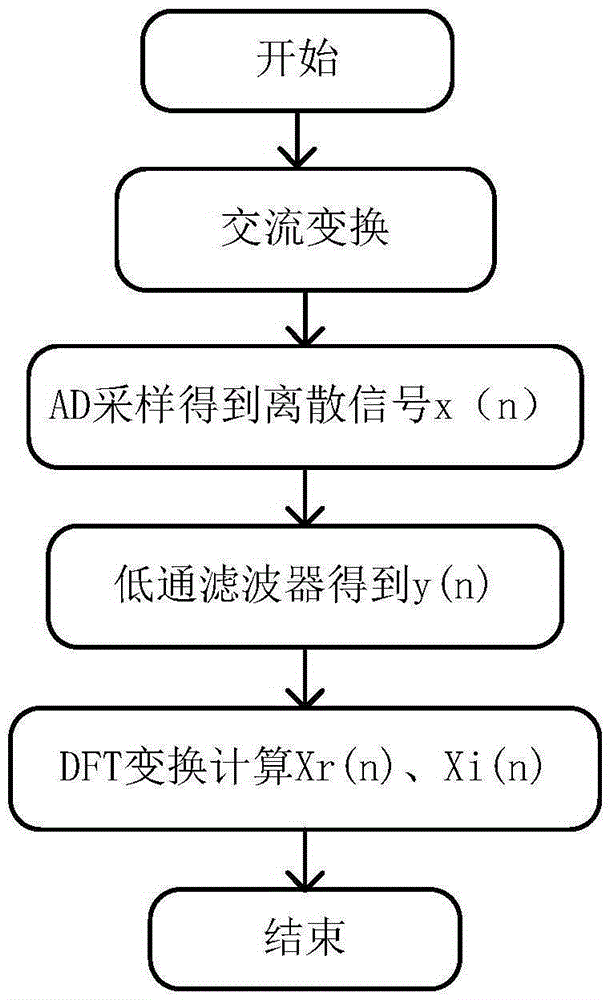
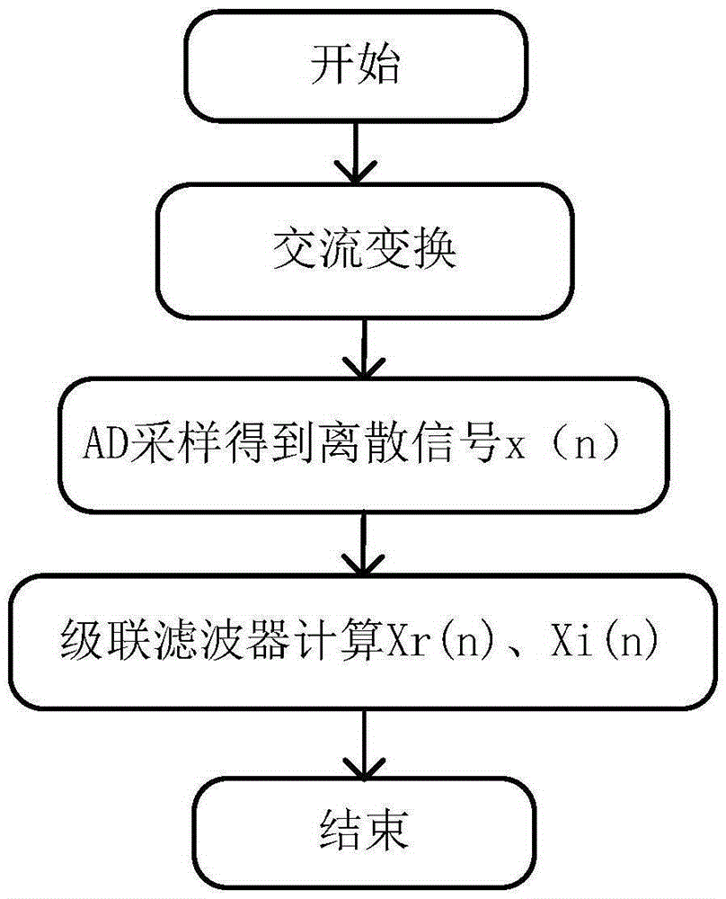
[0044] From the analysis of the background technology, it can be seen that during the DFT calculation, each sampling point needs to be FIR filtered, that is, the FIR filter is nested during the DFT calculation, resulting in a sharp increase in the amount of calculation.

[0045] Suppose the transfer functions of the two filters are H 1 (Z), H 2 (Z), the transfer function H(Z)=H after cascading filters 1 (Z)·H 2 (Z), the corresponding filter coefficient can be obtained from the transfer function. The FIR filter cascade DFT is actually two filter cascades, and the corresponding transfer function can also be solved theoretically. However, when the filtering order of the FIR is large, it is very difficult to calculate the cascaded transfer function, and it is easy to make mistakes. The filter coefficients after filter cascading are directly solved, avoiding the complicated process of solving the transfer function.

[0046] The specific process is as follows:

[0047] Expand ...


PUM


Abstract

The invention provides a high efficiency FIR filter cascade DFT algorithm. Convolution definition is utilized, a calculation formula for R(M+N-1) and I(M+N-1) filtering coefficients of an M-order FIR filter cascade N-point DFT algorithm is derived, after a filtering coefficient after cascade is calculated in an off-line mode, two independent filters are integrated into one filter, calculation efficiency is improved, a problem of large operand caused by filter cascade is effectively solved.

Description

technical field [0001] The invention belongs to the field of power system protection and automation and is used for improving the calculation efficiency of FIR filter cascaded DFT algorithm. Background technique [0002] In power system applications, many signal processing and analysis are based on the analysis of the sine fundamental wave. At present, the most widely used power system protection devices, measurement and control devices, synchrophasor measurement devices and primary and secondary signal processing software are using DFT calculates the fundamental wave quantity. DFT comes from the Fourier series, and the algorithm itself has a filtering effect, which can filter out integer harmonics. [0003] The Fourier algorithm for computing a continuous periodic signal x(t) is: [0004] X r n = 2 T ∫ - T ...

Claims


Application Information

Patent Timeline
IPC IPC(8): G01R23/167
CPCG01R23/167
Inventor 余高旺王莉李江林蔺立杨凯张艳超刘树猛马小燕过锐马仪成
Owner XUJI GRP
Why Eureka
Try Eureka