Solar steam generation device

A technology of solar steam and generating device, applied in the field of solar energy application, can solve the problems affecting service life, production service, complex structure, etc., and achieve the effect of prolonging service life, improving reliability and good heat collection effect

Inactive Publication Date: 2016-03-02
海宁泰尔欣新材料有限公司
View PDF12 Cites 3 Cited by
  • Summary
  • Abstract
  • Description
  • Claims
  • Application Information

AI Technical Summary

Problems solved by technology

[0002] The research, development and utilization of solar energy as a new energy source. Since the 1950s, scientists from all over the world have carried out a lot of exploration and research on how to absorb the sun's thermal energy and convert thermal energy. The success of vacuum heat collection technology in the 1980s is The utilization of solar energy has created conditions, but most of the vacuum solar heat collectors in the prior art are low-temperature vacuum heat collectors, which only use solar energy to provide some domestic hot water for people, and the effective utilization rate is low, which cannot provide a large amount of industrial and agricultural products that need high-temperature heat energy. Production services, that is, it is impossible to use solar energy to provide high-temperature heat energy to generate steam. In the existing one, the patent number is 201220243897.7. The structural stability of the heat pipe can still be improved. The application number is 201010273232.6 solar steam rapid generator. The temperature of the heat transfer pipe is too high during use, which will damage the insulation material and affect its service life. As an improvement direction, the design A solar steam generating device with good heat collection effect, stable performance and durability is of great significance to the utilization of solar energy

Method used


Image

  • Solar steam generation device
  • Solar steam generation device
  • Solar steam generation device

Examples


Embodiment approach 2

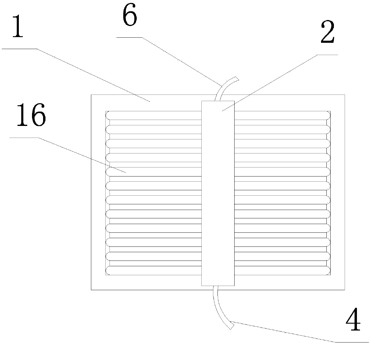
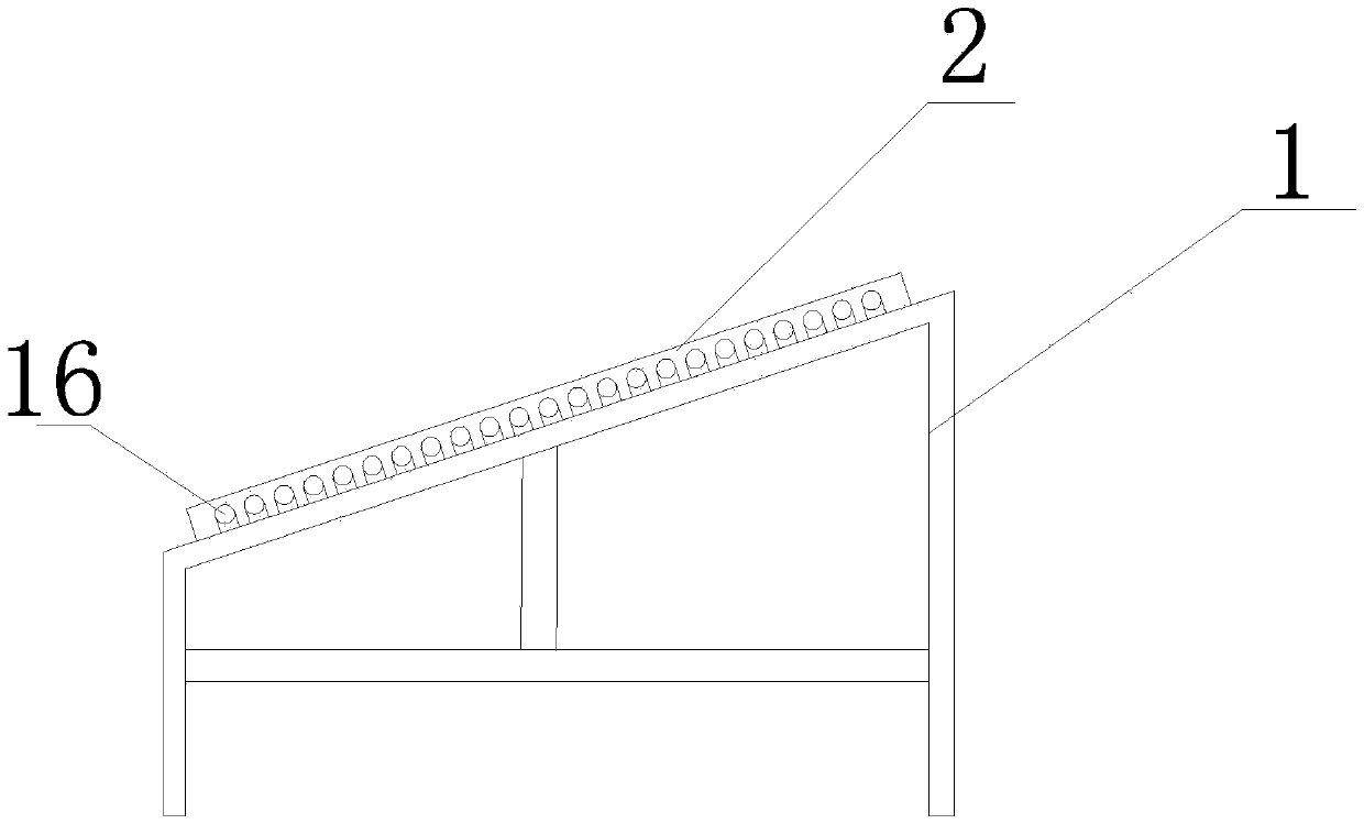
[0029]The second embodiment is one heat exchange tube 11, one heat exchange tube 11, and the heat exchange tubes 11 alternately enter the inner tube 7 of the left and right heat collecting tubes 16 to form a serpentine distribution. This embodiment has only one steam outlet 18. However, in the process of steam generation, the transmission path is long, the water is fully evaporated, the quality of the output steam is high, and the temperature and pressure of the steam are also high. This kind of solar steam generating device can quickly reach 120 Celsius to 200 degrees Celsius, it can also be connected in series through the headers 2, 50 heat collector tubes 16 as a group, a group of modules can generate 2KW of heat, the heat collection effect is good, the performance temperature is high, and it is durable. Multiple solar steam generating devices can be connected in series or in parallel to generate a large amount of saturated steam, series can generate higher temperature steam...


PUM


Abstract

The invention provides a solar steam generation device which has the beneficial effects of being good in heat collection effect, stable in performance and durable. The solar steam generation device comprises a header (2) and heat collection tubes (16) connected with the header (2). The header (2) is provided with at least one heat exchange tube (11), the heat exchange tubes (11) enter inner tubes (7) of the corresponding heat collection tubes (16) in sequence, and the steam outlet ends (18) of the heat exchange tubes (11) are located inside or outside the header (2). The inner tubes (7) are provided with heat transfer fins (5), and the cross section of each heat transfer fin (5) is in an arc shape or a W shape. If the cross section of each heat transfer fin (5) is in the arc shape, the outer surfaces of the arc-shaped parts are provided with first grooves (19) and second grooves (20) for installing the heat exchange tubes (11); and if the cross section of each heat transfer fin (5) is in the W shape, the W-shaped parts each comprise two wings and a middle portion, the wings abut against the walls of the inner tubes (7), and the heat exchange tubes (11) are arranged at the middle portions. The parts, located in the header (2), of the heat exchange tubes (11) are provided with heat insulation bodies (12) used for isolating the parts from heat insulation materials (13) with which the header (2) is filled.

Description

technical field [0001] The invention relates to the technical field of solar energy application, in particular to a solar steam generating device. Background technique [0002] The research, development and utilization of solar energy as a new energy source. Since the 1950s, scientists from all over the world have carried out a lot of exploration and research on how to absorb the sun's thermal energy and convert thermal energy. The success of vacuum heat collection technology in the 1980s is The utilization of solar energy has created conditions, but most of the vacuum solar heat collectors in the prior art are low-temperature vacuum heat collectors, which only use solar energy to provide some domestic hot water for people, and the effective utilization rate is low, which cannot provide a large amount of industrial and agricultural products that need high-temperature heat energy. Production services, that is, it is impossible to use solar energy to provide high-temperature h...

Claims


Application Information

Patent Timeline
Patent Type & Authority Applications(China)
IPC IPC(8): F22B1/00F24J2/30F24J2/10F24J2/00F24S10/30F24S23/70
CPCY02E10/44
Inventor 周强郑敏华
Owner 海宁泰尔欣新材料有限公司
Why Eureka
Try Eureka