A laser based on the combination of self-Raman and opo
What is AI technical title?
AI technical title is built by Patsnap AI team. It summarizes the technical point description of the patent document.
A laser and combined technology, applied in the field of lasers, can solve the problems of difficult adjustment, high cost, complex laser cavity structure, etc., and achieve the effect of convenient adjustment and compact structure
Inactive Publication Date: 2018-09-21
CHINA UNIV OF PETROLEUM (EAST CHINA)
View PDF4 Cites 0 Cited by
Summary
Abstract
Description
Claims
Application Information
AI Technical Summary
This helps you quickly interpret patents by identifying the three key elements:
Problems solved by technology
Method used
Benefits of technology
Problems solved by technology
The structure of the entire laser cavity is relatively complex, the cost is relatively high, and the adjustment is difficult
Method used
Image
Click on the blue label to locate the original text in one second.
Reading with bidirectional positioning of images and text.
Examples
Embodiment 1
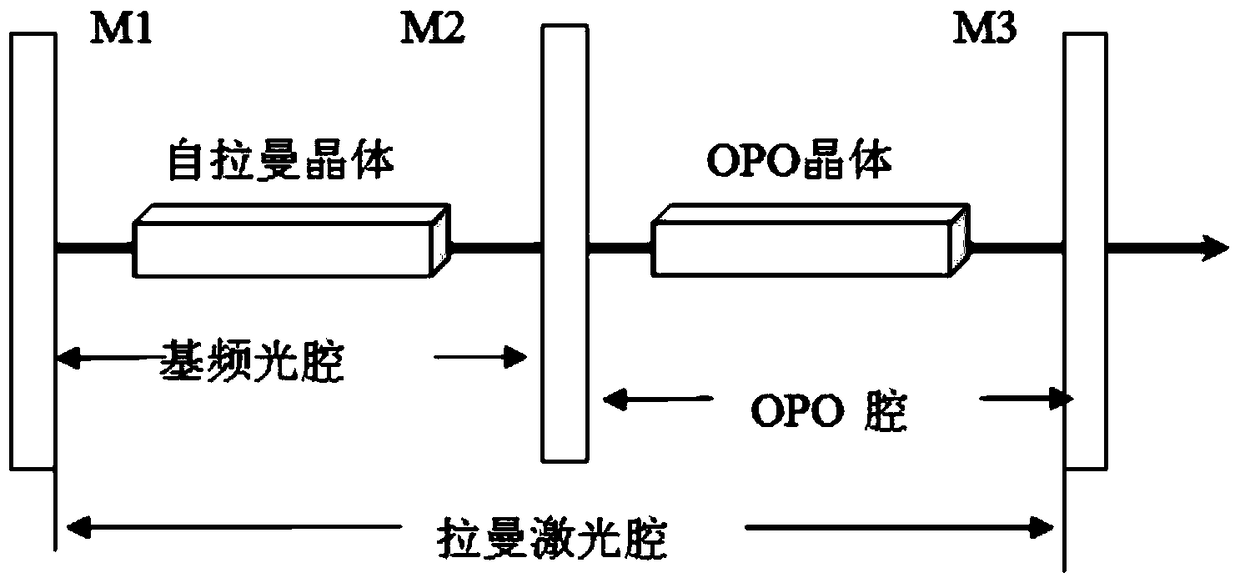
[0049] like figure 1 As shown, cavity mirror M1 and cavity mirror M2 form a fundamental frequency optical cavity, M2 and cavity mirror M3 form an OPO cavity, M1 and M3 form a Raman optical cavity,
[0050] The fundamental frequency optical cavity is isolated from the OPO optical cavity, and the Raman optical cavity covers the fundamental frequency optical cavity and the OPO optical cavity.
[0051] Coating requirements are as follows: M1 is highly reflective to fundamental frequency light and Raman light; one side of M2 is to fundamental frequency light, and the other is highly reflective to parametric light (signal light and (or) idler light). High transmittance of Raman light; M3 is highly reflective to Raman light and partially transmits to parametric light (signal light and (or) idler light);
[0052] Self-Raman crystal coating enhances the transmission of fundamental frequency light and Raman light;
[0053] OPO crystal coating is anti-reflective to Raman light and para...
Embodiment 2
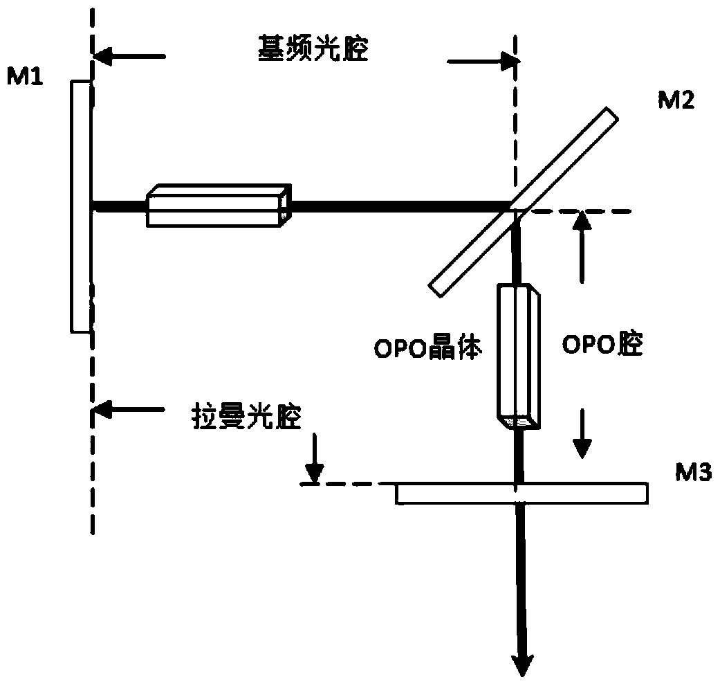
[0057] like figure 2 As shown, the line connecting the first cavity mirror and the second cavity mirror forms a right angle or other angles with the line connecting the second cavity mirror and the third cavity mirror, and other settings are consistent with the first embodiment.
Embodiment 3
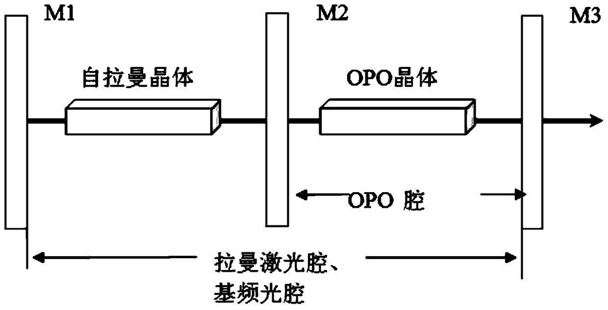
[0059] like image 3 As shown, M1 and M3 form a fundamental frequency optical cavity, which is also a Raman optical cavity, and M2 and M3 form an OPO cavity. The fundamental frequency light and the Raman optical cavity coincide.
[0060] Coating requirements: M1 is highly reflective to fundamental frequency light and Raman light; M2 is highly reflective to parametric light (signal light and (or) idler light) on one side, and highly transparent to Raman light and fundamental frequency light on both sides; M3 is highly reflective to parametric light (signal light and (or) idler light) Fundamental frequency light and Raman light are highly reflective, and partly transmitted to parametric light (signal light and (or) idler light);
[0061] Self-Raman crystal coating enhances the transmission of fundamental frequency light and Raman light;
[0062] OPO crystal coating is anti-reflective to fundamental frequency light, Raman light and parametric light (signal light and (or) idler ...
PUM
Abstract
The invention discloses a laser based on the combination of self-Raman and OPO, which includes a first cavity mirror, a second cavity mirror and a third cavity mirror, and a self-pulling laser is arranged between the first cavity mirror and the second cavity mirror. Mann crystal, an OPO crystal is arranged between the second cavity mirror and the third cavity mirror, and the first cavity mirror, the second cavity mirror and the third cavity mirror are coated with a coating, so that the first cavity mirror, the second cavity mirror A fundamental frequency optical cavity is formed between the cavity mirrors, an OPO cavity is formed between the second cavity mirror and the third cavity mirror, a Raman laser cavity is formed between the first cavity mirror and the third cavity mirror, and the pumping light is completed from the Raman crystal Conversion into fundamental frequency light, conversion of fundamental frequency light into Raman light wavelength conversion, Raman light is used as a pump source to pump the OPO crystal, and completes the wavelength conversion from Raman light to OPO parametric light. Use the self-Raman medium to realize the operation of the self-Raman laser, and then use the Raman light as the pump source to pump the OPO medium to complete the optical parameter conversion, and at the same time apply the tuning technology to generate long-wavelength tunable laser.
Description
technical field [0001] The invention relates to a laser based on the combination of self-Raman and OPO. Background technique [0002] Nonlinear optical frequency conversion technology is one of the important research contents and research hotspots in the field of optics at present. Its purpose is to seek coherent light of various wavelengths to meet the needs of practical applications. Stimulated Raman scattering (Stimulated Ramanscattering, SRS) is an efficient nonlinear frequency conversion process, and it is an effective way to realize laser frequency conversion. In recent years, with the development of crystal Raman material growth technology, solid-state Raman lasers based on the stimulated Raman scattering effect of crystals have attracted widespread attention due to their small size, high efficiency, and good stability. It has important applications in the fields of medical treatment, transportation, measurement and national defense, and has become a current research...
Claims
Application Information
Patent Timeline
Application Date:The date an application was filed.
Publication Date:The date a patent or application was officially published.
First Publication Date:The earliest publication date of a patent with the same application number.
Issue Date:Publication date of the patent grant document.
PCT Entry Date:The Entry date of PCT National Phase.
Estimated Expiry Date:The statutory expiry date of a patent right according to the Patent Law, and it is the longest term of protection that the patent right can achieve without the termination of the patent right due to other reasons(Term extension factor has been taken into account ).
Invalid Date:Actual expiry date is based on effective date or publication date of legal transaction data of invalid patent.

