Deep ultraviolet light laser with tunable wavelength

A deep ultraviolet light and laser technology, applied in the field of optical waveguide theory, can solve the problems of large dispersion and transmission loss, small mode field overlap area, and high laser power density, so as to improve conversion efficiency, overcome group velocity mismatch, and reduce suppression. Effect

Inactive Publication Date: 2013-10-09
BEIJING UNIV OF TECH
View PDF2 Cites 10 Cited by
  • Summary
  • Abstract
  • Description
  • Claims
  • Application Information

AI Technical Summary

Problems solved by technology

However, the laser power density required for nonlinear generation of inert gases is high (up to 1014W / cm 2 ), the experiment must be pumped with tens of femtosecond ultrashort pulses and high average power, which limits the choice of pump sources; and each fiber end is equipped with a pressure chamber and a control device that increases the complexity of practical applications Sex, in 9×10 4 Under Pa pressure, there are also requirements for the structure of photonic crystal fiber
[0005] The second type is to realize the phase matching between the fundamental wave and the high-order mode of the third harmonic in the solid-core photonic crystal fiber. Due to the large group velocity mismatch and the small mode field overlapping area, the conversion efficiency is extremely low. Only 0.05%
Although the conversion efficiency reaches 4%, there are other nonlinear effects due to the shrinking core diameter
[0007] To sum up, due to the relatively large dispersion and transmission loss, the deep ultraviolet laser is directly generated in the photonic crystal fiber at present, and there are problems such as low conversion efficiency and complicated experimental equipment.

Method used


Image

  • Deep ultraviolet light laser with tunable wavelength
  • Deep ultraviolet light laser with tunable wavelength
  • Deep ultraviolet light laser with tunable wavelength

Examples


Embodiment Construction

[0061] The present invention will be further described in conjunction with the accompanying drawings.

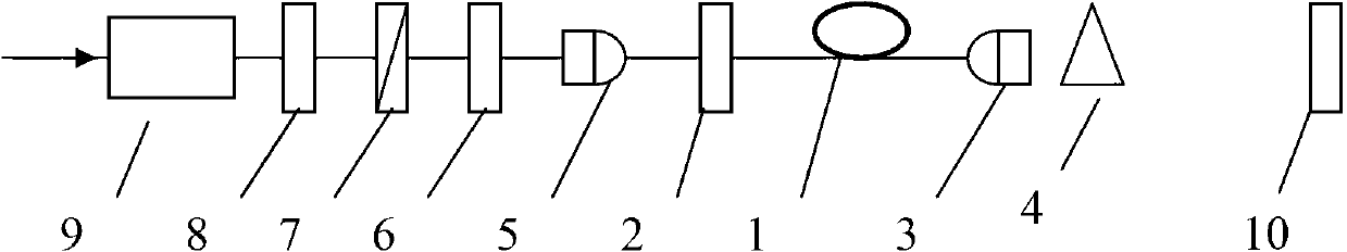
[0062] like figure 1 As shown, the wavelength tunable deep ultraviolet laser includes: highly nonlinear optical material 1, high reflection mirror 2, output beam collimator 3, beam splitter 4, pump optical coupler 5, dispersion compensation element 6, polarization A controller 7, a pump light power controller 8, an optical isolator 9 and a spectral filter lens 10.

[0063] The highly nonlinear optical material 1 is placed at the back end of the high reflective mirror 2, the output beam collimator 3 is placed at the output end of the highly nonlinear optical material 1, and the pump optical coupler 5 is placed close to the input end of the high reflective mirror 2 , the dispersion compensation element 6 is placed in front of the incident end of the pump optical coupler 5, the polarization controller 7 is placed in front of the incident end of the dispersion compensation elem...


PUM


Abstract

The invention discloses a deep ultraviolet light laser with the tunable wavelength and belongs to the technical field of photoelectrons and laser. High nonlinear optical materials are placed at the emergent end of a high reflective mirror, an output beam collimator is placed at the output end of the high nonlinear optical materials, a pump light coupler is placed at the input end close to the high reflective mirror, a dispersion compensation element is placed in front of the incidence end of the pump light coupler, a polarization controller is placed in front of the incidence end of the dispersion compensation element, a pump light power controller is placed in front of the incidence end of the polarization controller, an optical isolator is arranged at the incidence end of pump light, and a spectral filtering piece is placed at the emergent end of the whole light path. The deep ultraviolet light laser with the tunable wavelength overcomes the defect of large group velocity mismatching between the pump light and deep ultraviolet light and does not need multiple frequency components. The optical device is simple and high in conversion efficiency. Due to the fact that the pump wavelength, pump light power and the polarization state of the pump light are adjustable within a certain range, the tunable laser output of a deep ultraviolet laser wave band is achieved.

Description

technical field [0001] The invention belongs to the field of optoelectronics and laser technology, and relates to the fields of optical waveguide theory and technology, nonlinear optics, photonics and technology. It is suitable for applications in scientific and technological fields such as laser lithography, optical data storage, medicine, spectroscopy, photochemistry, molecular biology, strong field physics, and ultrafast process detection. Background technique [0002] With the development of all-solid-state laser technology and new deep-ultraviolet nonlinear crystals, cascade frequency doubling or summing of near-infrared light (NIR) is currently an effective method to obtain deep-ultraviolet laser. However, the above methods are limited by factors such as large group velocity mismatch, the length and transparency of nonlinear materials, and the complexity of optical devices (such as phase delay lines, dispersion compensation, and non-collinear optical parametric amplifi...

Claims


Application Information

Patent Timeline
Patent Type & Authority Applications(China)
IPC IPC(8): H01S3/08H01S3/108
Inventor 王丽詹仪
Owner BEIJING UNIV OF TECH
Why Eureka
Try Eureka