Fiber grating string structure and preparation method thereof

A fiber grating string, fiber grating technology, which is applied to the structure/shape of cladding fiber, optical waveguide light guide, active medium, etc., can solve the problems of unfavorable output of high-power laser, excessive extra fusion loss, complicated production process, etc. Achieve the effect of reducing the loss and risk of laser transmission, improving the suppression ability, and making the production process simple

Pending Publication Date: 2022-03-18
四川橙科通信技术研究院有限责任公司
View PDF0 Cites 1 Cited by
  • Summary
  • Abstract
  • Description
  • Claims
  • Application Information

AI Technical Summary

Problems solved by technology

[0003] The traditional method of preparing chirped tilted fiber gratings is mainly based on the excimer ultraviolet laser phase mask method. The phase mask and the optical fiber are rotated, the length of the actual grating is limited by the size of the phase mask grating area, the manufacturing process is complicated and the flexibility is poor
[0004] In addition, the more the number of chirped tilted fiber gratings, the better the nonlinear suppression, but the increase in the number will cause too much additional fusion loss. In fiber lasers, chirped tilted fiber gratings are generally placed between the output coupling fiber grating and the cladding light. It is very unfavorable to achieve high-power laser output by adding several additional welding points between the strippers

Method used


Image

  • Fiber grating string structure and preparation method thereof
  • Fiber grating string structure and preparation method thereof
  • Fiber grating string structure and preparation method thereof

Examples


Embodiment Construction

[0032] The following will clearly and completely describe the technical solutions in the embodiments of the present invention with reference to the accompanying drawings in the embodiments of the present invention. Obviously, the described embodiments are only some, not all, embodiments of the present invention. Based on the embodiments of the present invention, all other embodiments obtained by persons of ordinary skill in the art without making creative efforts belong to the protection scope of the present invention.

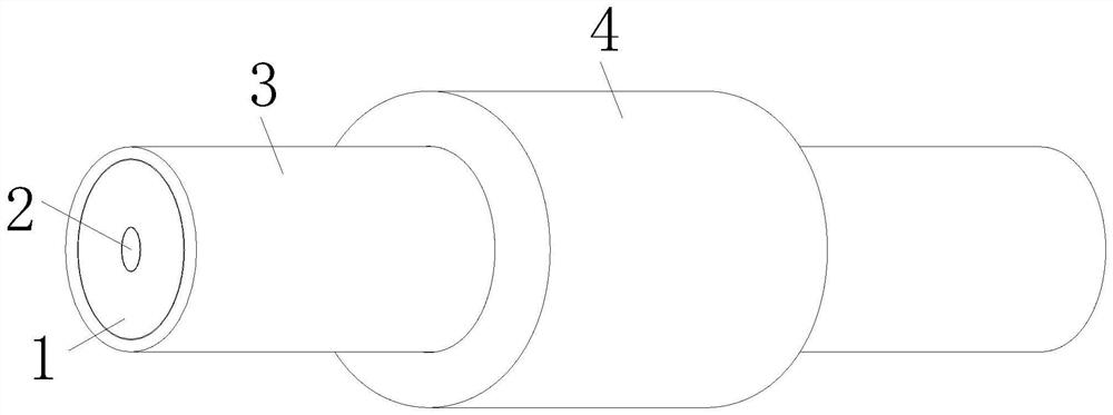
[0033] see Figure 1-5 , the present invention provides the following technical solutions: a fiber grating string structure, comprising a fiber core 2, the front section of the fiber core 2 is provided with an output coupling fiber grating 5, and the middle section of the fiber core 2 is provided with a chirped tilted fiber grating string 6 , the outer side of the optical fiber core 2 is coated with a cladding light stripper, and the outer side of the cladding...


PUM


Abstract

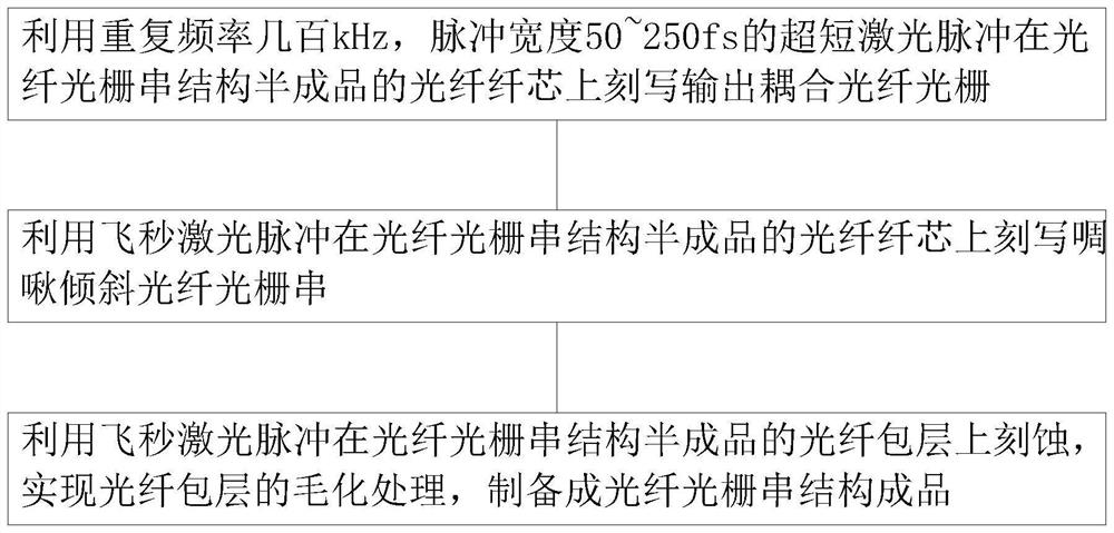
The invention discloses a fiber bragg grating string structure, which belongs to the technical field of fiber lasers and comprises a fiber core, an output coupling fiber bragg grating is arranged at the front section of the fiber core, a chirp tilted fiber bragg grating string is arranged at the middle section of the fiber core, and a cladding light stripper is coated on the outer side of the fiber core. The outer side of the cladding light stripper is sleeved with a water cooling shell; the invention also discloses a preparation method of the fiber grating string structure. Full femtosecond laser processing is adopted, chirp inclined fiber bragg grating inscribing can be completed only by enabling the optical fiber and the laser beam cladding to form an inclination angle, a mask plate is not needed, the optical fiber does not need to be rotated, the length of the actually-manufactured grating is not limited by the size of a phase mask plate grid region, the manufacturing process is simple, and flexibility is good.

Description

technical field [0001] The invention belongs to the technical field of fiber lasers, and in particular relates to a fiber grating string structure and a preparation method thereof. Background technique [0002] With the development of fiber laser-related technologies, nonlinear effects are one of the key factors restricting the increase of output power of high-power fiber laser systems. There are many methods for suppressing stimulated Raman scattering in fiber lasers. Among them, chirped tilted fiber gratings have The unique mode coupling characteristics have unique advantages when used as a filter, and can be used as stimulated Raman scattering and stimulated Brillouin filter suppression. [0003] The traditional method of preparing chirped tilted fiber gratings is mainly based on the excimer ultraviolet laser phase mask method. The phase mask and the optical fiber are rotated, and the length of the actually manufactured grating is limited by the size of the phase mask gr...

Claims


Application Information

Patent Timeline
Patent Type & Authority Applications(China)
IPC IPC(8): H01S3/067G02B6/02H01S3/04
CPCG02B6/02123G02B6/02076H01S3/0675H01S3/0407H01S3/06712
Inventor 湛欢姜伟李儒陈昌勇任浩
Owner 四川橙科通信技术研究院有限责任公司
Why Eureka
Try Eureka