Cell sheet assembly, cell sheet matrix and solar cell assembly

A cell and module technology, applied in the field of solar cells, can solve the problems of large amount of connecting cables, decreased cell efficiency, damage to cells and conductive tapes, etc., and achieves the effect of reducing the length of use, improving the overall power, and reducing the amount of use.

Pending Publication Date: 2018-01-09
BYD CO LTD
View PDF0 Cites 0 Cited by
  • Summary
  • Abstract
  • Description
  • Claims
  • Application Information

AI Technical Summary

Problems solved by technology

[0002] In the crystalline silicon solar cell in the related art, there are 2-3 silver busbars on the light-receiving side and the backlight side respectively as the positive and negative electrodes of the cell. These silver busbars not only consume a large amount of silver paste, but also block the incident light. resulting in a decrease in the efficiency of the cell
In addition, since the positive and negative electrodes are respectively distributed on the light-receiving surface and the backlight surface of the cell, when the cells are connected in series, it is necessary to use a conductive tape to weld the negative electrode on the light-receiving surface of the cell to the positive electrode on the backlight surface of the adjacent cell. As a result, the welding process is cumbersome and the use of more welding materials is problematic. Moreover, it is easy to cause damage to the battery sheet and the conductive strip during welding and subsequent lamination processes.
[0003] In addition, the cell matrix in the related art is usually composed of 72 or 60 cells connected in series to form three loops consisting of six strings of cells. At this time, at least three diodes are generally required to make each loop A diode is added for bypass protection. Since the diode is usually placed in the junction box of the battery, the cost of the integrated junction box is increased, which increases the structural complexity of the battery. When connecting in series again, the amount of connecting cables is very large, and a lot of materials are wasted, resulting in an increase in the cost of the power station

Method used


Image

  • Cell sheet assembly, cell sheet matrix and solar cell assembly
  • Cell sheet assembly, cell sheet matrix and solar cell assembly
  • Cell sheet assembly, cell sheet matrix and solar cell assembly

Examples


Embodiment 1

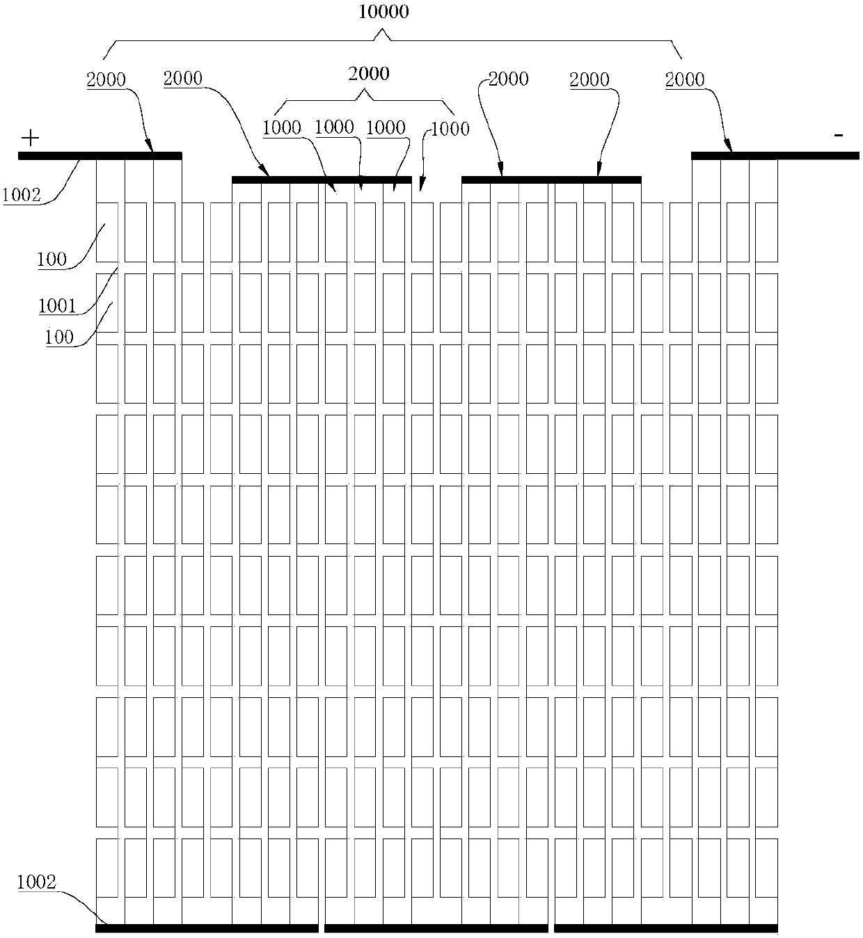
[0128] refer to Figure 5-Figure 9 The cell sheet 100 includes: a silicon wafer 1, a front conductive member, a side conductive member 3, a first electrode 4, a back electric layer 60, and a second electrode 5, wherein the front conductive member is a front grid line layer 2, and the silicon wafer 1 can be It includes a silicon substrate 11 , a front first type diffusion layer 12 , a side spacer 13 and a back side spacer 14 .

[0129] The silicon substrate 11 is sheet-shaped, and the two surfaces in the thickness direction of the silicon substrate 11 are respectively a light-receiving surface and a backlight surface, and the light-receiving surface and the backlight surface are connected through side surfaces. Wherein, the front first-type diffusion layer 12 is arranged on the light-receiving surface of the silicon substrate 11, for example, in a preferred embodiment of the present invention, the front-side first-type diffusion layer 12 is covered with the light-receiving surf...

Embodiment 2

[0172] refer to Figure 10-Figure 14 , the structure of this embodiment 2 is substantially the same as that of embodiment 1, wherein the same components use the same reference numerals, the difference is only that: the second region in embodiment 1 is provided with a back electric layer 60, and the back electric layer 60 is provided with the second electrode 5, and the second region in this embodiment 2 is provided with the back second type diffusion layer 15, and the back second type diffusion layer 15 is provided with the back second gate line layer 6 and the second electrode 5.

[0173] The battery sheet 100 includes: a silicon wafer 1, a front conductive part, a side conductive part 3, a first electrode 4, a second grid line layer 6 and a second electrode 5 on the back side, wherein the front conductive part is the front grid line layer 2, and the silicon chip 1 may include a silicon substrate 11, a front first-type diffusion layer 12, a back-side second-type diffusion la...

Embodiment 3

[0190] refer to Figure 15-Figure 19 , the structure of this embodiment 3 is substantially the same as that of embodiment 2, wherein the same components use the same reference numerals, the only difference is that the first region and the second region in embodiment 2 have no intersection and no contact with each other, However, in Embodiment 3, the first area and the second area have no intersection and are in contact with each other, that is, the contour line of the first area is in contact with the contour line of the second area.

[0191] Specifically, the first region and the second region have no intersection and are in contact with each other, and the first electrode 4 is arranged on the first region, that is to say, the first electrode 4 can be directly or indirectly arranged on the first region, at this time, the second An electrode 4 is provided on the backlight surface of the silicon wafer 1 and is opposite to the first area, that is, projected along the thickness d...


PUM


Abstract

The invention discloses a cell sheet assembly, a cell sheet matrix and a solar cell assembly. The solar sheet assembly comprises cell sheets and conductive belts. The cell sheets and the conductive belts are successively arranged longitudinally. Each cell sheet comprises a silicon sheet, a front conductive piece arranged on a light receiving face of the silicon sheet, two electrodes arranged on abacklight face of the silicon sheet and a side conductive piece which is arranged on the side surface of the silicon sheet and electrically connected between the front conductive piece and one electrode. The two electrodes of each cell sheet longitudinally extend and are separated at an interval transversally. The extension direction of the conductive belts is the same as that of the electrodes, the conductive belts conduct two electrodes which are close to each other and arranged on adjacent two cell sheets so as to allow the adjacent cell sheets to be serially or parallelly connected. According to the invention, use length of the conductive belts can be effectively reduced; use quantity of the conductive belts can be reduced; heat effects caused by the conductive belts are reduced; and the whole power of the cell sheet assembly is improved.

Description

technical field [0001] The invention relates to the technical field of solar cells, in particular to a cell assembly, a cell matrix and a solar cell assembly. Background technique [0002] In the crystalline silicon solar cell in the related art, there are 2-3 silver busbars on the light-receiving side and the backlight side respectively as the positive and negative electrodes of the cell. These silver busbars not only consume a large amount of silver paste, but also block the incident light. As a result, the efficiency of the battery sheet is reduced. In addition, since the positive and negative electrodes are respectively distributed on the light-receiving surface and the backlight surface of the cell, when the cells are connected in series, it is necessary to use a conductive tape to weld the negative electrode on the light-receiving surface of the cell to the positive electrode on the backlight surface of the adjacent cell. As a result, the welding process is cumbersome...

Claims


Application Information

Patent Timeline
Patent Type & Authority Applications(China)
IPC IPC(8): H01L31/05
CPCY02E10/50
Inventor 孙翔姚云江田野姜占锋
Owner BYD CO LTD
Why Eureka
Try Eureka