
Integrated railway signal machine

A railway signal machine and signal machine technology, applied in the direction of railway signals, visual signals, railway car body parts, etc., can solve the problems of many boxes and basic accessories, large floor space, and difficult maintenance

Pending Publication Date: 2021-09-07
CHINA RAILWAY ELECTRIFICATION BUREAU GROUP THIRD ENG
View PDF2 Cites 0 Cited by
  • Summary
  • Abstract
  • Description
  • Claims
  • Application Information

AI Technical Summary

Problems solved by technology

[0002] The traditional signal installation method is signal A + wiring box B (such as Figure 4 ), the formation of this installation method is a problem left over from the age when the industrial level was low. The foundations of signal machines and wiring boxes have always been made of solid concrete products, which occupy a large area, are heavy, difficult to install, and difficult to maintain. The function of the signal machine can only be realized by adding a box, and there are many accessories between the box and the foundation, and the installation process is complicated

Method used


Image

  • Integrated railway signal machine
  • Integrated railway signal machine
  • Integrated railway signal machine

Examples


Embodiment

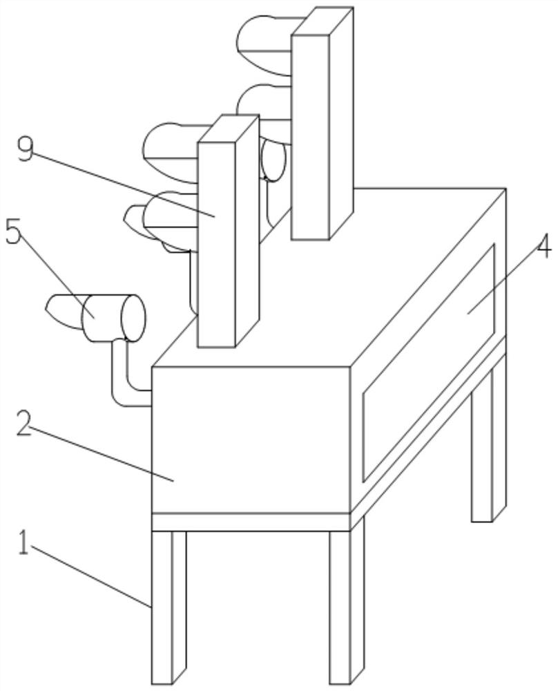
[0023] Example: see figure 1 , figure 2 , image 3 , Figure 4 and Figure 5 , in the figure, 1-first foundation, 2-second foundation, 3-fixing bolt, 4-cover body, 5-departure indicator, 6-lighting transformer, 7-indicator installation hole, 8-terminal block, 9-Signal machine mechanism, 10-Cable entry hole (indicated position, but not limited to this position), 11-Signal machine mechanism lead hole; A-Signal machine, B-Junction box.

[0024] The integrated railway signal machine foundation includes the first foundation and the second foundation. The second foundation is detachably arranged on the first foundation through fixing bolts, and the second foundation is a hollow structure, and the second foundation area is provided with a cover. Departure indication The indicator is arranged on the front part of the second foundation through the installation hole of the indicator, and communicates with the inner cavity of the second foundation, the lighting transformer is arrang...

Embodiment 2

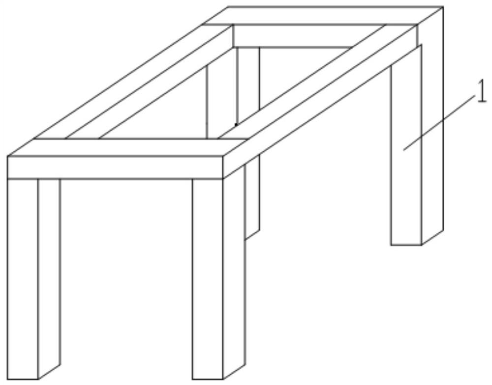
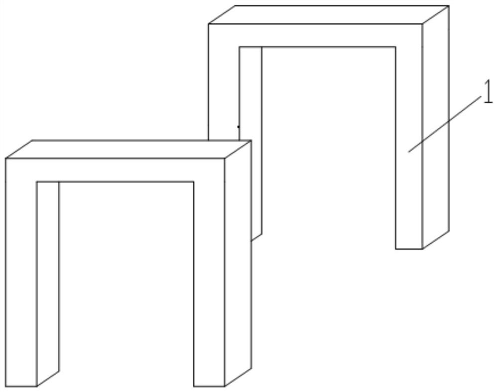
[0034] This embodiment is obtained by changing the technical features such as the structure of the first foundation 1 on the basis of the first embodiment, and the rest of the technical features are the same as the first embodiment, and the similarities will not be repeated here, wherein the detailed description of the technical features is changed It is: the first foundation 1 is a rectangular frame foundation (wherein, the rectangular frame foundation is two door-shaped frames or a rectangular overall frame, or other frames with stable support, and its material is iron, steel, aluminum alloy, glass steel, wood, Metal or non-metal materials such as composite materials).

[0035] By replacing the concrete foundation in Embodiment 1 with a rectangular frame foundation, the construction of the concrete foundation and the transportation of building materials are further reduced, which facilitates transportation, reduces the intensity of personnel, reduces the construction period o...


PUM


Abstract

The invention discloses an integrated railway signal machine. The integrated railway signal machine comprises a first foundation and a second foundation, wherein the second foundation is detachably arranged on the first foundation, a cover body is arranged in the area of the second foundation, signal equipment comprises a signal mechanism, a starting indicator and a lighting transformer, the starting indicator is arranged on the second foundation corresponding to the first foundation through an indicator mounting hole and communicates with an inner cavity of the second foundation, the lighting transformer is arranged in the second foundation, and a signal mechanism is arranged at the top of the second foundation. Through cooperation between the foundations and the signal equipment, the signal foundations are arranged in the foundations to form an integrated structure, and compared with an existing split type base and a box body, a distribution box and connecting parts between the distribution box and the box body are omitted, meanwhile, the using length of a wire is reduced, and the occupied area of the signal machine is reduced.

Description

Technical field: [0001] The invention relates to a railway signal machine, in particular to an integrated railway signal machine foundation. Background technique: [0002] The traditional signal installation method is signal A + wiring box B (such as Figure 4 ), the formation of this installation method is a problem left over from the age when the industrial level was low. The foundations of signal machines and wiring boxes have always been made of solid concrete products, which occupy a large area, are heavy, difficult to install, and difficult to maintain. The function of the signal machine can only be realized by adding a box, and there are many accessories between the box and the foundation, and the installation process is complicated. Invention content: [0003] The technical problem to be solved by the present invention is: to overcome the deficiencies of the prior art, through the cooperation between the foundation and the signal equipment, the signal machine light...

Claims


Application Information

Patent Timeline
IPC IPC(8): E02D27/44B61L5/18
CPCE02D27/44B61L5/18
Inventor 汤国军黄红赵金锦陈亚萍江海源常建光董文武张远民刘贵平张萍
Owner CHINA RAILWAY ELECTRIFICATION BUREAU GROUP THIRD ENG
Learn More