Eureka AIR delivers breakthrough ideas for toughest innovation challenges, trusted by R&D personnel around the world.

Lens module colour-difference correction method, lens module colour-difference correction system, lens module and photographing equipment

A lens module and chromatic aberration technology, applied to color TV parts, color TV, color signal processing circuits, etc., can solve the problems of high cost, heavy testing workload, large error, etc., and achieve good results and simple solutions The effect of high accuracy of line and correction

Active Publication Date: 2016-03-02
GOERTEK OPTICAL TECH CO LTD
View PDF3 Cites 11 Cited by
  • Summary
  • Abstract
  • Description
  • Claims
  • Application Information

AI Technical Summary

Problems solved by technology

[0005] In the first step, you need to know the color difference between the lens module and the standard lens module at each color temperature value. You can first test the color temperature parameters of the lens module and the standard lens module at a color temperature of 5000K, and calculate the difference between the lens module and the standard lens module. The relative difference (for example, 8%) of the color temperature parameters of the sample lens module at 5000K color temperature, put the relative difference into the lens module, and calculate the color difference of the lens module at each color temperature value according to the relative difference Correction is equivalent to using the relative difference value at 5000K color temperature for color difference correction without considering the change of ambient color temperature in the first step. The error of this method is relatively large
[0006] Or, test several more color temperature values ​​in the first step, for example, test the color temperature parameters of the lens module and the standard lens module at 3000K, 5000K, and 6500K color temperature respectively, and calculate the color temperature parameters of the lens module and the standard lens module at 3000K , the relative difference of color temperature parameters at 5000K and 6500K color temperature (for example, the relative difference of color temperature parameters at 3000K color temperature is 6%, the relative difference of color temperature parameters at 5000K color temperature is 7%, and the relative difference of color temperature parameters at 8000K color temperature is The relative difference is 8%). When actually taking pictures, select the one closest to the current environment color temperature value from 3000K, 5000K, and 6500K, and use the relative difference value of the color temperature parameter corresponding to the closest color temperature value as the current environment The relative difference of the color temperature parameter of the color temperature value is used to correct the color difference. This method is slightly more accurate than the previous method, but it still uses several color temperature values ​​to represent all the color temperature values, and dynamic correction cannot be realized. And the test work Large quantity and high cost

Method used


Image

  • Lens module colour-difference correction method, lens module colour-difference correction system, lens module and photographing equipment
  • Lens module colour-difference correction method, lens module colour-difference correction system, lens module and photographing equipment
  • Lens module colour-difference correction method, lens module colour-difference correction system, lens module and photographing equipment

Examples


Embodiment Construction

[0024] Various exemplary embodiments of the present invention will now be described in detail with reference to the accompanying drawings. It should be noted that the relative arrangements of components and steps, numerical expressions and numerical values ​​set forth in these embodiments do not limit the scope of the present invention unless specifically stated otherwise.

[0025] The following description of at least one exemplary embodiment is merely illustrative in nature and in no way taken as limiting the invention, its application or uses.

[0026] Techniques, methods and devices known to those of ordinary skill in the relevant art may not be discussed in detail, but where appropriate, such techniques, methods and devices should be considered part of the description.

[0027] In all examples shown and discussed herein, any specific values ​​should be construed as exemplary only, and not as limitations. Therefore, other instances of the exemplary embodiment may have dif...


PUM


Abstract

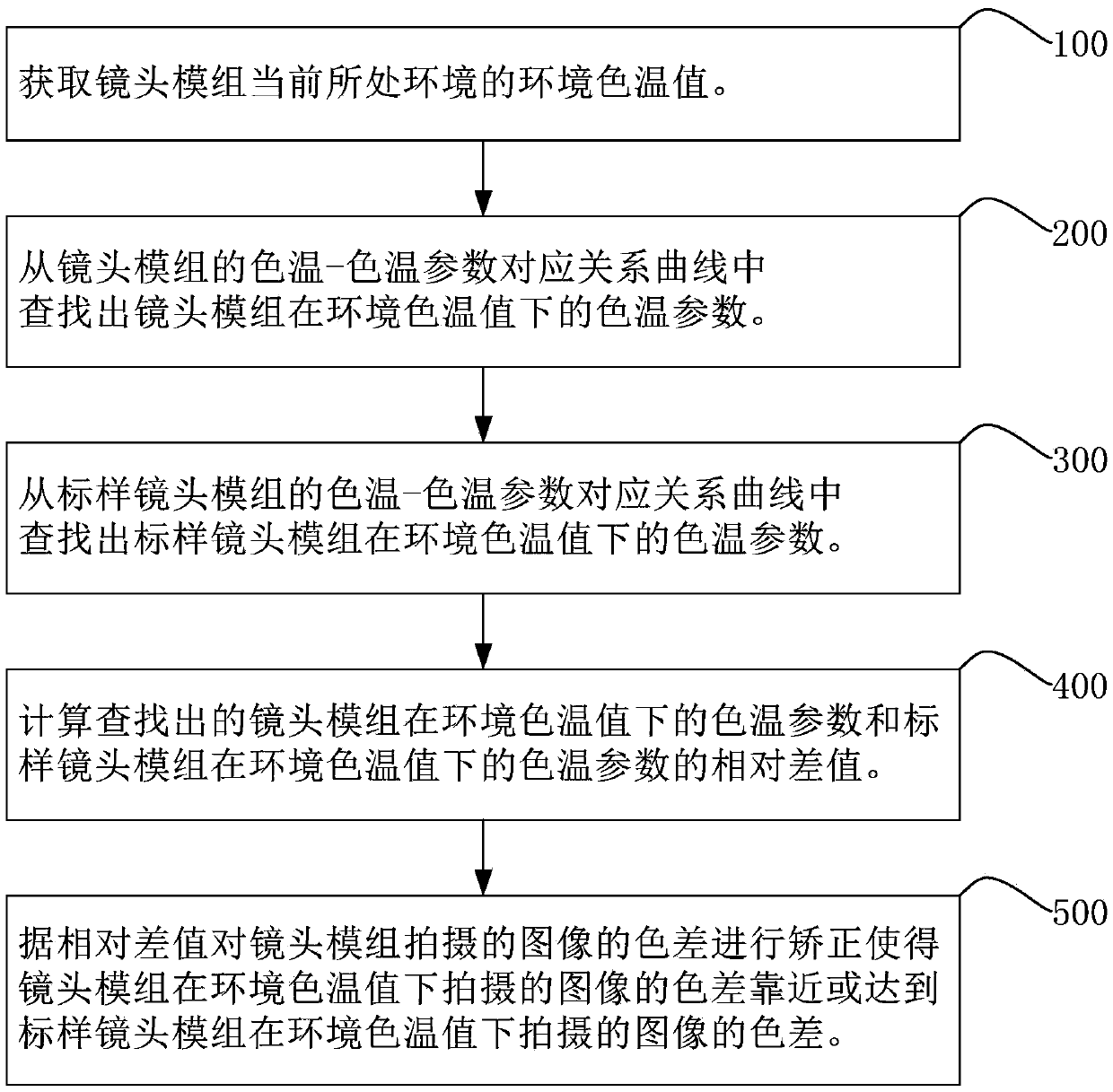
The invention discloses a lens module colour-difference correction method, a lens module colour-difference correction system, a lens module and photographing equipment. The lens module colour-difference correction method comprises the following steps: obtaining a current environmental colour temperature value at first; finding out a colour temperature parameter of the lens module under the environmental colour temperature value from a curve of a corresponding relationship between the colour temperature of the lens module and the colour temperature parameter; finding out a colour temperature parameter of a standard lens module under the environmental colour temperature value from a curve of a corresponding relationship between the colour temperature of the standard lens module and the colour temperature parameter; and calculating the relative difference value of the two, and correcting the colour difference of an image photographed by the lens module according to the relative difference value, such that the colour difference of the image photographed by the lens module under the environmental colour temperature value is close to or achieves the colour difference of an image photographed by the standard lens module under the environmental colour temperature value. According to the invention, the colour difference of the lens module can be dynamically corrected; the correction accuracy is high; and the effect is good.

Description

technical field [0001] The present invention relates to the technical field of image processing, and more specifically, to a method for correcting chromatic aberration of a lens module, a system for correcting chromatic aberration of a lens module, a lens module, and a photographing device. Background technique [0002] Existing camera equipment usually has a white balance calibration function, which performs white balance compensation on images captured by the lens module according to the white balance compensation coefficient corresponding to the color temperature value of the current environment where the camera device is located. [0003] Due to individual differences in sensor chips, lenses, and infrared filters (Infrared Radiation filters, IR chips), there are differences in imaging between lens modules of the same batch. The lens modules are all tested, and the white balance compensation coefficients of the lens modules at various color temperature values ​​are measur...

Claims


Application Information

Patent Timeline
Patent Type & Authority Applications(China)
IPC IPC(8): H04N9/097H04N9/73H04N23/16
CPCH04N23/16H04N23/88
Inventor 宋林东廖吉仁
Owner GOERTEK OPTICAL TECH CO LTD
Why Eureka
Eureka Blog
Learn More