
Vehicle radar adjustment control method

An adjustment control and radar technology, applied in the automotive field, can solve the problems of small detection range, small use range, and complex structure, and achieve the effects of reducing the range of detection blind spots, reducing costs, improving reliability and redundancy supplementary capabilities

Active Publication Date: 2016-03-09
ZHEJIANG GEELY AUTOMOBILE RES INST CO LTD +1
View PDF7 Cites 7 Cited by
  • Summary
  • Abstract
  • Description
  • Claims
  • Application Information

AI Technical Summary

Problems solved by technology

This invention needs to realize the safety warning function of the blind area through the master and slave control framework of the system, and the structure is complicated. In addition, the ultrasonic probes arranged on both sides of the vehicle body in this invention are fixed, and the detection range is small, which is not suitable for use under various working conditions. small range

Method used


Image

  • Vehicle radar adjustment control method

Examples


Embodiment Construction

[0023] The following are specific embodiments of the present invention and in conjunction with the accompanying drawings, the technical solutions of the present invention are further described, but the present invention is not limited to these embodiments.

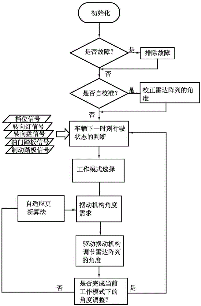
[0024] like figure 1 As shown, the vehicle radar adjustment control method includes the following steps:

[0025] Step 1: First judge whether there is a fault in the radar array, and display the installation position of the faulty radar component when the radar array is faulty, and then troubleshoot the fault. After the fault is rectified or when there is no fault, use the angle sensor to judge whether the current radar array needs Calibration, if necessary, judge whether the vehicle is in a stopped state, if it is in a stopped state, adjust the radar array, and complete the correction of the initial angle of the radar array through the swing mechanism; if it is not in a stopped state or does not need to be adjusted, enter...


PUM


Abstract

The present invention provides a vehicle radar adjustment control method, belonging to the technical field of automobiles. The problems of complex structure and small blind area detection range in the prior art are solved. The method comprises the steps of (1) judging whether a current radar array needs to be adjusted or not, if so, completing the correction of a radar array initial angle through a swing mechanism, and if not, entering into a normal working state, (2) after entering into the normal working state, judging the driving state of a vehicle at a next time, selecting a corresponding working mode in a working mode selector according to a judgment result, adjusting the radar array to a needed angle through the swing mechanism, and entering into a radar array swing angle adjustment period, and (3) in the radar array swing angle adjustment period, through an adaptive algorithm, maintaining the angle of the radar array at a needed adjustment angle. According to the method, while the cost of a whole automobile is reduced, the range of the blind area detection is increased.

Description

technical field [0001] The invention belongs to the technical field of automobiles, and relates to a vehicle radar regulation control method. Background technique [0002] When the vehicle is running, the driver observes the road and vehicle conditions on both sides and behind the vehicle through the rearview mirrors on both sides of the front window. Due to the insufficient field of view of the rearview mirror of the vehicle, there are always blind spots for visual observation on both sides of the vehicle window when the driver is driving, and the driver cannot observe whether there are vehicles or pedestrians in the area through the rearview mirror. Therefore, there are potential safety hazards in driving links such as vehicle lane changing and merging. [0003] In view of the above-mentioned blind spot problem, a large number of vehicles are currently equipped with active safety radars to avoid the blind spot problem. The radar layout is fixed. Due to the limited detecti...

Claims


Application Information

Patent Timeline
IPC IPC(8): G01S13/93G01S7/40
CPCG01S7/40G01S13/931G01S2013/9315
Inventor 孙伟
Owner ZHEJIANG GEELY AUTOMOBILE RES INST CO LTD
Learn More