Connection movement support shaft structure

A technology of movable support and support shaft, applied in the direction of connecting rod, shaft and bearing, mechanical equipment, etc., can solve the problems of low service life, support shaft wear, lack of flexibility, etc., to increase service life, slow down external force, reduce wear and tear Effect

Inactive Publication Date: 2016-03-16
果涛
View PDF0 Cites 2 Cited by
  • Summary
  • Abstract
  • Description
  • Claims
  • Application Information

AI Technical Summary

Problems solved by technology

[0002] In the prior art, the support shaft is usually used for the connection between machines, but the support of the prior art is usually fixed and lacks flexibility, and some mechanical connections just need flexibility; moreover, now The technical support shaft is often worn due to external force factors during use, resulting in a low service life

Method used


Image

  • Connection movement support shaft structure

Examples


Embodiment

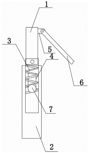
[0010] see figure 1 , connected to the movable support shaft structure, including the support shaft 1 and the shaft tube 2 connected to the bottom of the support shaft 1, a pin hole 4 is opened on the shaft tube 2, the pin hole 4 is rectangular, and a pin hole 4 is provided in the pin hole 4 pin, and the diameter of the pin cap 7 is longer than the width of the pin hole 4, and also includes a gasket, one end of the support shaft 1 is connected to one end of the gasket, the other end of the gasket is fixed on the shaft tube 2, and the gasket is also provided with a The force valve 3 and the force reducing valve 3 are arranged between the support shaft 1 and the shaft tube 2. One end of the force reducing valve 3 is connected to the bottom of the support shaft 1, and the pin cap 7 is engaged with the force reducing valve 3. During mechanical movement, the force reducing valve 3 The force valve 3 plays a role in slowing down the external force, and the force reducing valve 3 driv...


PUM


Abstract

The present invention discloses a connection movement support shaft structure, which comprises a support shaft and a shaft pipe connected to the bottom portion of the support shaft, wherein the shaft pipe is provided with a pin shaft hole, the pin shaft hole is rectangular, a pin shaft is arranged inside the pin shaft hole, the diameter of a pin shaft cap is longer than the width of the pin shaft hole, the connection movement support shaft structure further comprises a gasket, one end of the support shaft is connected to one end of the gasket, the other end of the gasket is fixed on the shaft pipe, the gasket is further provided with a force reducing valve, the force reducing valve is arranged between the support shaft and the shaft pipe, one end of the force reducing valve is connected to the bottom portion of the support shaft, the pin shaft cap is connected to the force reducing valve in a snapping manner, and the support shaft close to the top end is connected to a movable shaft. The connection movement support shaft structure of the present invention has advantages of external force reducing, wear reducing, service life prolonging, and flexibility enhancing.

Description

technical field [0001] The invention relates to a structure for connecting movable support shafts. Background technique [0002] In the prior art, the support shaft is usually used for the connection between machines, but the support of the prior art is usually fixed and lacks flexibility, and some mechanical connections just need flexibility; moreover, now The technical support shaft is often worn due to external force factors during use, resulting in a low service life. Contents of the invention [0003] Aiming at the shortcomings of the above-mentioned prior art, the present invention provides a structure for connecting movable support shafts, which can effectively solve the above-mentioned problems in the prior art. [0004] In order to achieve the above object, the technical solution adopted by the present invention is: connect the movable support shaft structure, including the support shaft and the shaft tube connected with the bottom of the support shaft, a pin hol...

Claims


Application Information

Patent Timeline
Patent Type & Authority Applications(China)
IPC IPC(8): F16C7/04
Inventor 果涛
Owner 果涛
Why Eureka
Try Eureka