
Fastening type lamp mounting plate

A mounting plate and snap-fit ​​technology, which is applied to lighting devices, lighting auxiliary devices, components of lighting devices, etc., can solve the problems of inconvenient disassembly and maintenance, and achieve the effect of convenient disassembly.

Inactive Publication Date: 2016-03-16
CHONGQING BEACON OPTOELECTRONICS TECH
View PDF0 Cites 0 Cited by
  • Summary
  • Abstract
  • Description
  • Claims
  • Application Information

AI Technical Summary

Problems solved by technology

[0002] With the development of society and the improvement of living standards, people's requirements for lamps are getting higher and higher. As a kind of lighting lamps, panel lamps are flat-shaped as a whole, and their light output is completely flat, and the light-emitting angle is wider and wider. It is used in hotels, meeting rooms, factories, residences and other places that require energy-saving and high color rendering index lighting. Nowadays, panel lights have become the mainstream product of indoor lighting, and their market share is expanding rapidly. There are many kinds of existing panel lights, including hanging Type, hanging type or ceiling type, generally composed of base, LED light-emitting components, light guide diffuser plate components and lamp covers, etc. At present, the general panel lights must be installed before the decoration is completed, and once the decoration is completed It is no longer possible to install this type of panel light. If there is a problem with the light in daily use, it is very inconvenient to disassemble and repair it

Method used


Image

  • Fastening type lamp mounting plate
  • Fastening type lamp mounting plate
  • Fastening type lamp mounting plate

Examples


Embodiment Construction

[0015] The present invention will be further described below with reference to the embodiments and accompanying drawings.

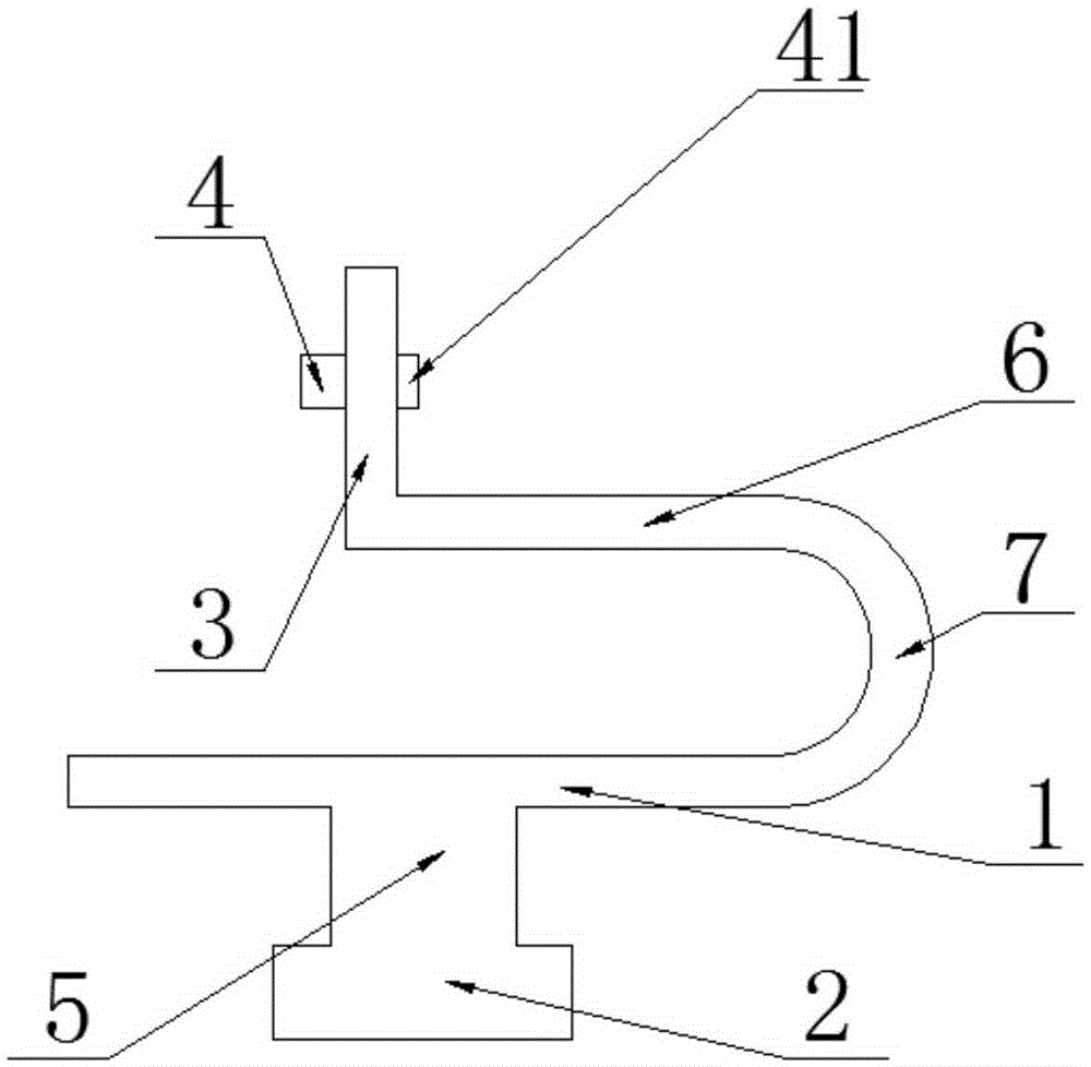
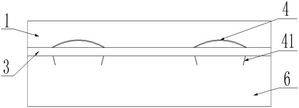
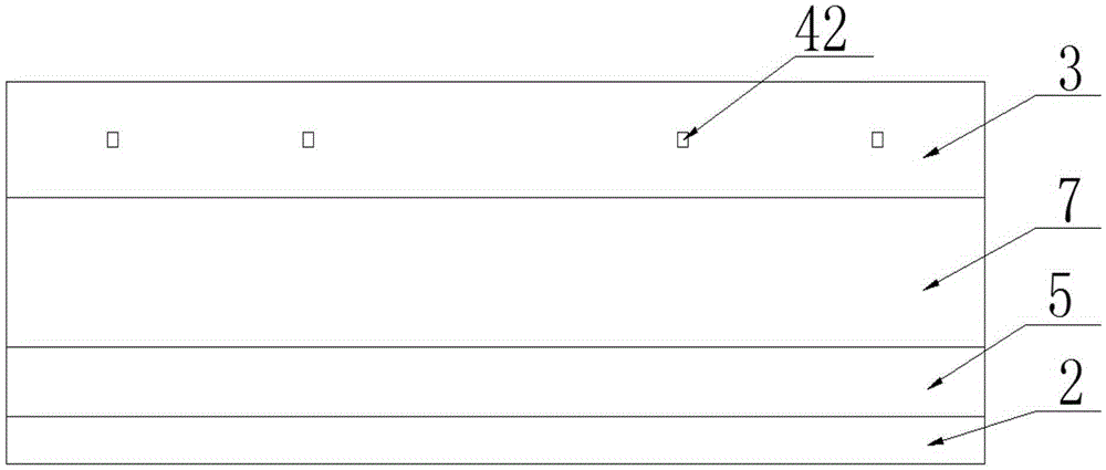
[0016] like Figure 1-3 As shown, a snap-fit ​​lamp mounting plate includes a lower clamping plate 1 and an upper clamping plate 6 arranged horizontally, and the inner side of the lower clamping plate 1 is located at the inner side of the upper clamping plate 6 Right above, an arc-shaped plate 7 is connected between the inner edge of the lower clamping plate 1 and the inner edge of the upper clamping plate 6, the opening of the arc-shaped plate 7 faces inward, and the outer edge of the upper clamping plate 6 is A baffle 3 is provided in the length direction, the lower edge of the baffle 3 is fixedly connected with the outer edge of the upper clamping plate 6, and the lower surface of the lower clamping plate 1 is provided with a mounting strip 5 along the length direction. 5. The lower surface is provided with a clamping strip 2 along the length directio...


PUM


Abstract

The invention discloses a fastening type lamp mounting plate. The fastening type lamp mounting plate comprises a lower clamping plate and an upper clamping plate, the two of which are arranged horizontally; a curved plate is connected between an inner edge of the lower clamping plate and an inner edge of the upper clamping plate; an opening of the curved plate is inward; a baffle plate is arranged at an outer edge of the upper clamping plate in a length direction; a lower edge of the baffle plate is fixedly connected with the outer edge of the upper clamping plate; a mounting strip is arranged on a lower surface of the lower clamping plate in the length direction; a clamping strip is arranged on a lower surface of the mounting strip in the length direction; the clamping strip is wider than the mounting strip; at least one elastic piece is arranged on an outer side surface of the baffle plate. According to the fastening type lamp mounting plate, the mounting plate is inserted into a lamp mounting frame by use of the mounting strip and the clamping strip and then fastened to a keel in a lamp mounting reserved hole; as the elastic piece is arranged on the panel lamp mounting plate, the elastic piece is deformed during clamping, such that a lamp can be clamped in the lamp reserved hole.

Description

technical field [0001] The invention relates to a component of a lighting device, in particular to a snap-fit ​​lamp mounting plate. Background technique [0002] With the development of society and the improvement of living standards, people's requirements for lamps are getting higher and higher. As a kind of lighting lamps, panel lamps are flat as a whole, their light output is completely flat, and the lighting angle is wider and wider. It is used in hotels, conference rooms, factories, residences and other places that require energy-saving and high color rendering index lighting. Nowadays, panel lights have become the mainstream products of indoor lighting, and the market share is rapidly expanding. There are many kinds of existing panel lights, including hanging It is generally composed of a base, LED light-emitting components, light guide diffuser components and lamp covers. At present, the general panel lights must be installed before the decoration is completed. Once ...

Claims


Application Information

Patent Timeline
Patent Type & Authority Applications(China)
IPC IPC(8): F21V21/03F21V17/16
CPCF21V21/03F21V17/164
Inventor 邵群
Owner CHONGQING BEACON OPTOELECTRONICS TECH
Learn More