Filter Insert

A filter device and filter element technology, which is applied in the direction of membrane filter, dispersed particle filter, mechanical equipment, etc., to achieve the effect of easy flow away

Active Publication Date: 2016-03-23
GE JENBACHER
View PDF14 Cites 1 Cited by
  • Summary
  • Abstract
  • Description
  • Claims
  • Application Information

AI Technical Summary

Problems solved by technology

The disadvantage of this solution, however, is the unavoidable bypass of the gas through the drain holes

Method used


Image

  • Filter Insert
  • Filter Insert
  • Filter Insert

Examples


Embodiment Construction

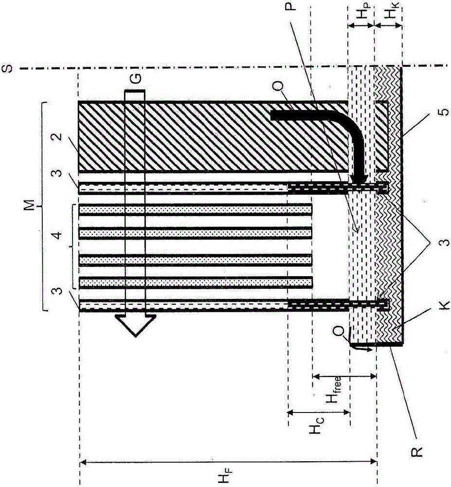
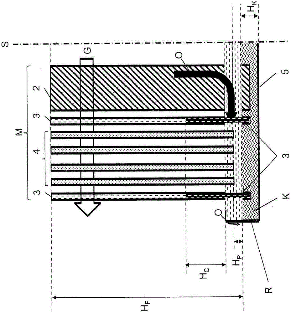
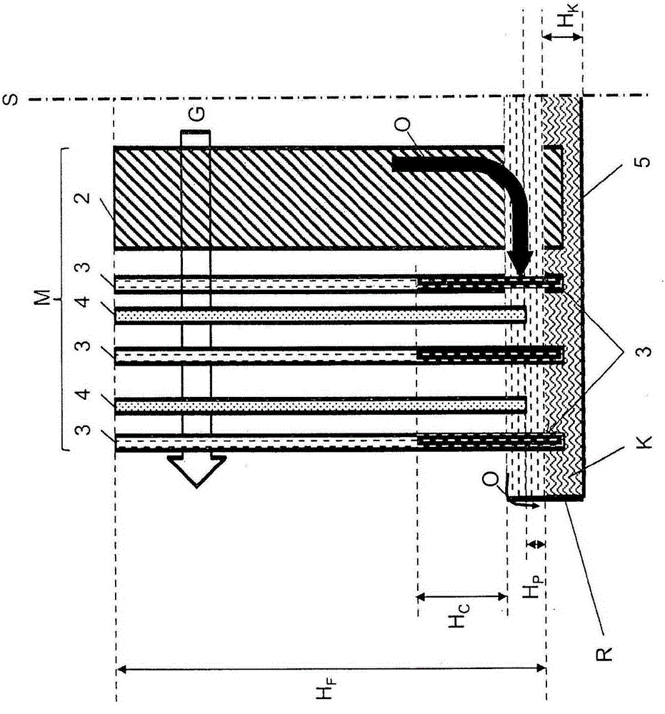
[0048] figure 1 An exemplary embodiment of a filter insert 1 is shown for separating suspended particles of a liquid from a gas flow G, in particular for separating liquid droplets from an aerosol-carrying gas. exist figure 1 The filter insert 1 shown in is of cylindrical design. The symmetry is characterized by the axis of symmetry S. Therefore, only the left half of the rotationally symmetrical structure is shown in the cross-sectional view.

[0049] Individual layers with different filter media can be seen in this arrangement, which together form a media group M. FIG.

[0050] Element 1 has a height H F .

[0051] The gas or gas flow G first flows through the filter medium 2 to then flow through the fine filter 4 via the first filter layer 3 having a capillary effect. Outside this arrangement in the flow direction there is again a layer 3 with a capillary effect, through which layer the now purified gas flow leaves the filter insert 1 .

[0052] The air flow G flows ...


PUM

PropertyMeasurementUnit
heightaaaaaaaaaa

Abstract

A filter insert for the separation of liquid droplets from a gas flow including: a media packet comprising layer portions of filter media, wherein in operation a gas flow to be cleaned passes through the media packet, and a bottom which is arranged in the lower region of the filter insert in relation to a discharge flow direction of a liquid separated from the gas flow, wherein a passage for the liquid, that extends over the radius of the filter insert, is provided between the filter medium for fine separation of the media packet and the bottom, or within the media packet.

Description

technical field [0001] The invention relates to a filter insert for separating liquid particles from a gas flow having the features of the preamble of claim 1 , a filter device having such a filter insert and the use of the filter device for internal combustion engines. Background technique [0002] A common purpose in technology is to separate liquid droplets from a gas stream. [0003] Separating devices used for this are often constructed in such a way that a generally cylindrical filter insert (filter cartridge) is inserted into the housing, through which the gas flow to be cleaned flows radially through. In this case, the throughflow can take place from the circumference inwards or vice versa. A typical filter element consists of a media pack (group of filter media) that is secured to the cover face by a securing section. [0004] The filter media incorporated into the filter element must fulfill two main purposes: [0005] - separation of entrained liquids by differ...

Claims


Application Information

Patent Timeline
Patent Type & Authority Applications(China)
IPC IPC(8): B01D46/00B01D46/24F01M13/04
CPCB01D46/10B01D46/12B01D46/003B01D46/0031B01D2275/10B01D46/62B01D46/2411F01M13/04F01M2013/0438
Inventor G·瓦尔
Owner GE JENBACHER
Why Eureka
Try Eureka