Electromagnetic valve

A solenoid valve and solenoid coil technology, applied in the field of solenoid valves, can solve problems such as hindering the plunger's rushing action, and achieve the effects of easy outflow and reduced pressure loss

Active Publication Date: 2011-11-09
SAGINOMIYA SEISAKUSHO INC
View PDF8 Cites 10 Cited by
  • Summary
  • Abstract
  • Description
  • Claims
  • Application Information

AI Technical Summary

Problems solved by technology

Therefore, especially as described in Patent Document 4, when the spherical valve body is held by the front end of the plunger, oil is accumulated between the valve body and the plunger, and the smooth operation of the plunger is hindered by the viscosity of the oil. jerk action problem

Method used


Image

  • Electromagnetic valve
  • Electromagnetic valve
  • Electromagnetic valve

Examples


Embodiment Construction

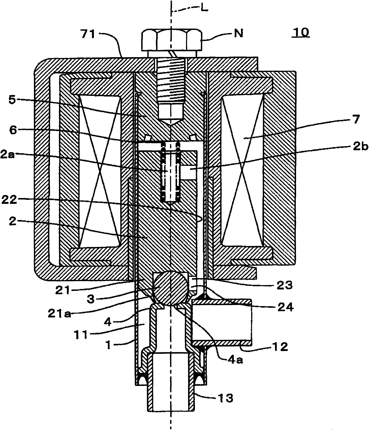
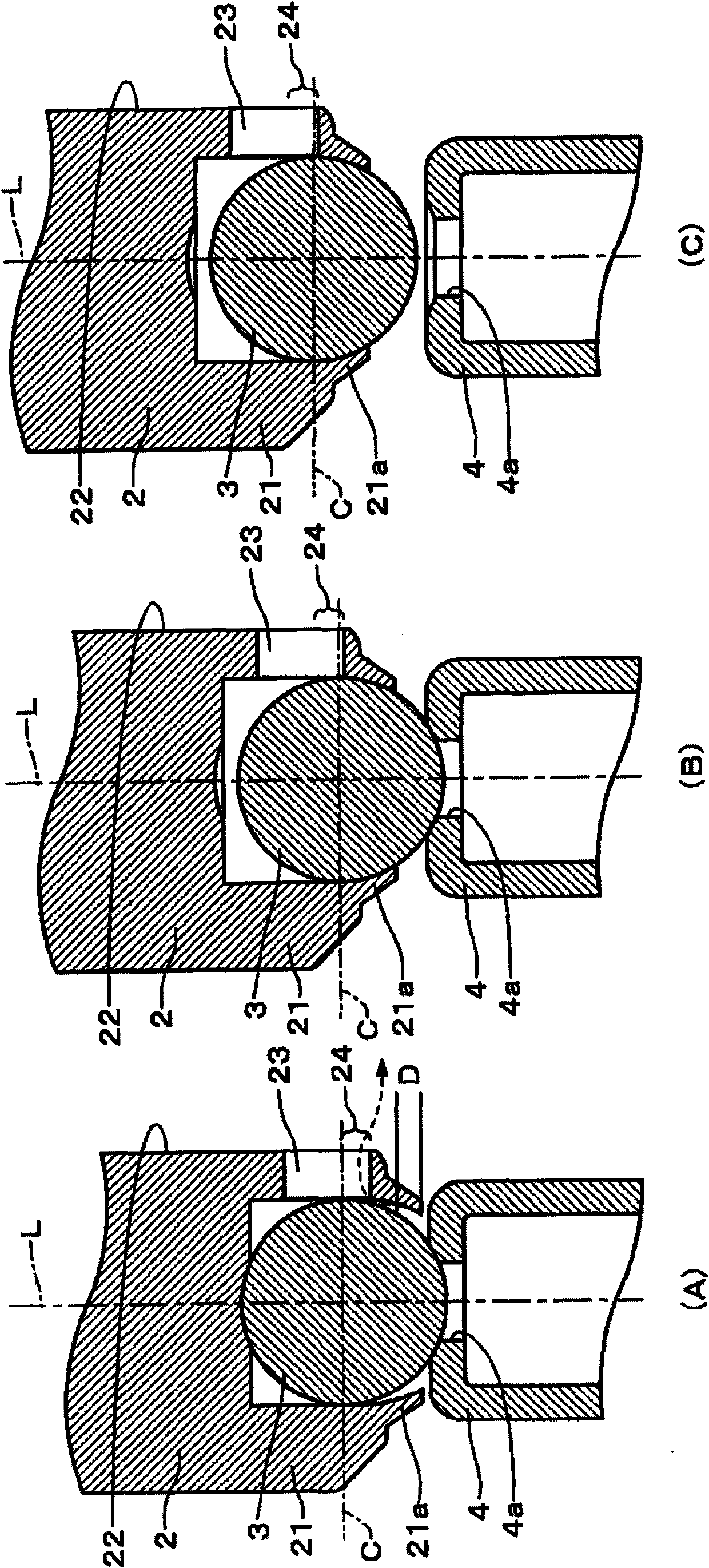
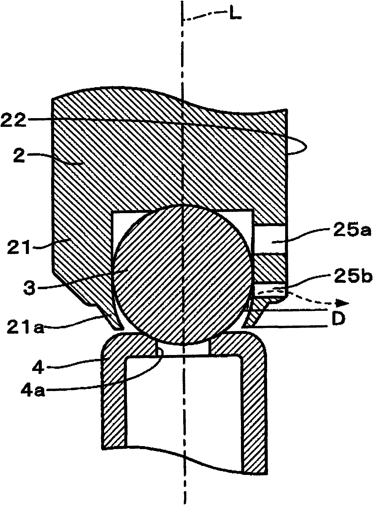
[0029] Next, embodiments of the solenoid valve of the present invention will be described with reference to the drawings. figure 1 is a longitudinal sectional view of the solenoid valve 10 of the embodiment when no power is applied, figure 2 It is an enlarged view of important parts when the solenoid valve 10 operates, figure 2 (A) indicates the state when no power is applied, figure 2 (B) represents the first state at the time of power-on, figure 2 (C) shows the second state at the time of power-on. Such as figure 1 As shown, the solenoid valve 10 of this embodiment includes: a cylindrical plunger tube 1 forming a valve housing 11; a plunger 2 arranged in the plunger tube 1; and a spherical valve element held by the plunger 2. 3; a cylindrical valve seat 4 fitted at the lower end of the plunger tube 1; an attractor 5 fixed at the upper end of the plunger 1; a coil spring 6 compressed between the plunger 2 and the attractor 5; And the electromagnetic coil 7 arranged i...


PUM


Abstract

The invention relates to an electromagnetic valve. Spherical valve core is maintained at the front end of a plunger. In the electromagnetic valve, the plunger and the valve core undergo a kicking through electrifying a solenoid, and smooth kicking can be conducted through reducing the influence by viscosity of non-compressibility fluid like oil. The spherical valve core (3) is disposed in a valvecore retaining portion (21) at the lower part of the plunger. The valve core (3) is maintained by a pawl portion (21a). A gap (D) is disposed between the valve core (3) and the pawl portion (21a). (figure 2) A big path (23) is formed at the valve core retaining portion (21) at a D-shaped cutting face (22) of the plunger (2). A part of a valve seat (4) side of the big path (23) forms a communicating path (24). The non-compressibility fluid accumulated between the pawl portion (21a) and the valve core (3) is discharged through the communicating path (24), reducing the viscosity influence of thenon-compressibility fluid.

Description

technical field [0001] The present invention relates to holding a spherical valve core at the front end of a plunger, energizing an attractor by energizing an electromagnetic coil to attract the plunger, and engaging the valve core with a valve seat having a shape corresponding to the spherical valve core, Specifically, the separate solenoid valve relates to a solenoid valve in which a valve body and a plunger are suddenly operated when the valve body is separated from a valve seat. Background technique [0002] Conventionally, among electromagnetic valves, as an electromagnetic valve that causes a valve core and a plunger to perform an abrupt action when the valve core is separated from the valve seat, there are, for example, Japanese Patent Laid-Open No. 2001-41340 (Patent Document 1), Japanese Patent Laid-Open 2003-269642 A (Patent Document 2), JP-A No. 10-227370 (Patent Document 3), and JP-A No. 10-78155 (Patent Document 4). In this electromagnetic valve, the attractor ...

Claims


Application Information

Patent Timeline
Patent Type & Authority Applications(China)
IPC IPC(8): F16K31/06
Inventor 剑持大一郎
Owner SAGINOMIYA SEISAKUSHO INC
Why Eureka
Try Eureka