

Ultrasonic vibration micro-foaming injection moulding device and ultrasonic vibration micro-foaming injection moulding method for plastic inspection well
A technology of plastic inspection wells and ultrasonic vibration, applied in the coating and other directions, can solve the problems of high consumption of plastic raw materials, low foaming efficiency, low product strength, etc., and achieve the effects of improving mechanical strength, enhancing mechanical strength, and eliminating weld lines.
- Summary
- Abstract
- Description
- Claims
- Application Information
AI Technical Summary
Problems solved by technology
Method used
Image

Examples
Embodiment 1
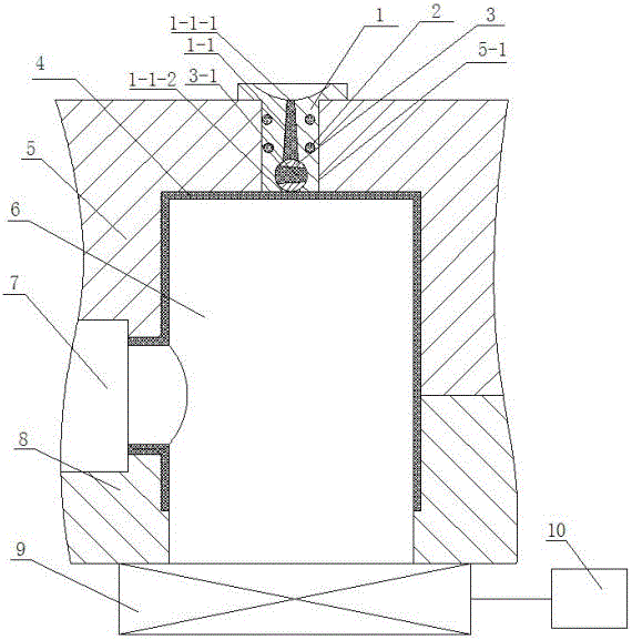
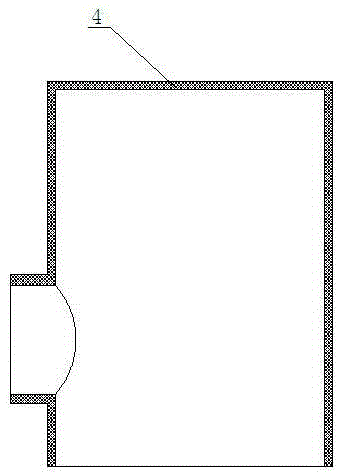
[0037] Embodiment 1: see attached figure 1 ~ attached Figure 5 , an ultrasonic vibration micro-foaming injection molding device for a plastic inspection well, comprising a fixed template 5, a movable template 8, a mold core and a hot runner system, an ultrasonic vibration device 9, and a control system 10, and the mold core includes a mold main core 6 , side-drawn core 7, the mold core is located between the fixed template 5 and the movable template 8, the side-drawn core 7 is adjacent to the main mold core 6 of the mold, and a mold core is provided between the fixed template 5 and the movable template 8 The mold cavity 11, the hot runner system is arranged on the fixed template 5, and the fixed template 5 is provided with a through cavity 5-1, and the hot runner system includes a sprue sleeve 1 embedded in the through cavity 5-1 of the fixed template 5, The heater 2 arranged on the outer edge of the sprue bushing 1, the sprue 1-1, the rotatable steering switch 3 arranged on...
Embodiment 2
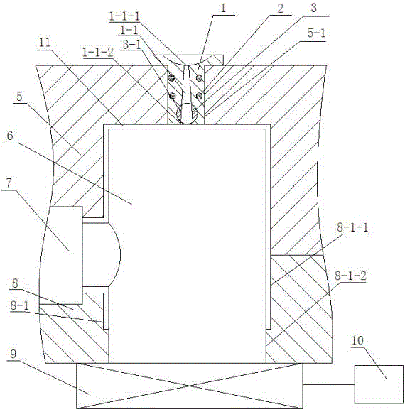
[0052] Embodiment 2: see attached figure 1 ~ attached Figure 5 , a plastic inspection well ultrasonic vibration micro-foaming injection molding device, the matching gap between the arc-shaped protrusion 7-1 of the side-drawing core 7 and the arc-shaped groove 6-1 of the main mold core 6 in this embodiment is 0.05mm; The lower end clearance of the mold main core 6 is matched with the second through hole 8-1-2 of the stepped through hole 8-1 on the movable template 8, and the matching clearance is 0.03mm; the steering switch 3 is a cylinder valve. All the other structures are the same as in Example 1.
[0053] The injection molding method using the ultrasonic vibration micro-foaming injection molding device for plastic inspection wells includes two stages of injection molding and micro-foaming. The first is injection molding. The injection molding includes the following steps:
[0054] (1) First, prepare before injection molding and plasticize the injection molding machine. A...
PUM
| Property | Measurement | Unit |
|---|---|---|
| Diameter | aaaaa | aaaaa |
| Diameter | aaaaa | aaaaa |
| Diameter | aaaaa | aaaaa |
Abstract
Description
Claims
Application Information