A dynamic prestressed clamping device for spinal implants and its installation method

A clamping device and prestressing technology, applied in the direction of spinal implants, joint implants, joint implants, etc., can solve problems such as vertebral tension, compression force, shear force and torque cannot be effectively transmitted, Achieve the effect of reducing the risk of slippage and improving effective transmission

Inactive Publication Date: 2017-09-29
贵州省黔南布依族苗族自治州中医医院
View PDF1 Cites 0 Cited by
  • Summary
  • Abstract
  • Description
  • Claims
  • Application Information

AI Technical Summary

Problems solved by technology

However, when this dynamic clamping device is in use, when the fulcrum is destroyed, the filler rotates around the fulcrum, and the filler still has the risk of relative sliding when pressing against the elastic connection element, causing tension between adjacent vertebrae, Compression, shear and torque are not transmitted efficiently

Method used


Image

  • A dynamic prestressed clamping device for spinal implants and its installation method
  • A dynamic prestressed clamping device for spinal implants and its installation method
  • A dynamic prestressed clamping device for spinal implants and its installation method

Examples


Embodiment Construction

[0052] The present invention will be further described below with reference to the drawings and embodiments.

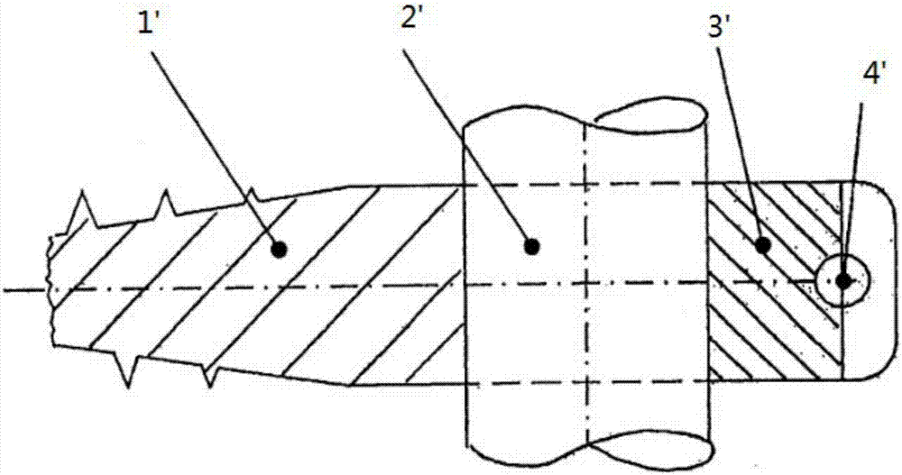
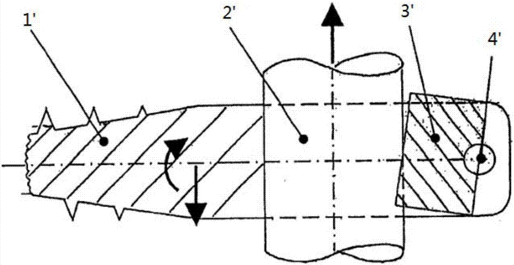
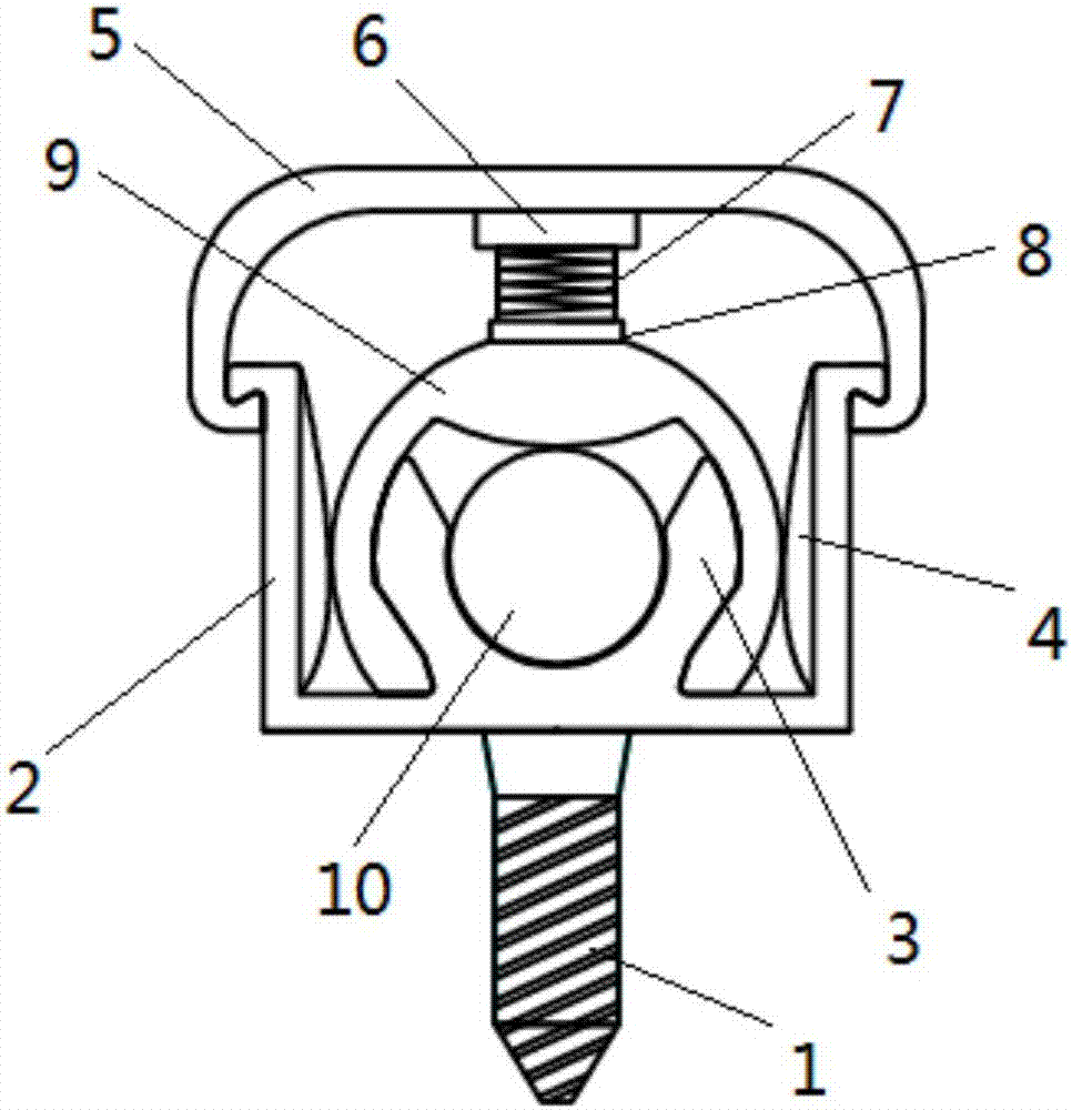
[0053] Such as Figure 1-3 As shown, a dynamic pre-stress clamping device for spinal implants includes a screw 1, a U-shaped member 2, a support 3, a cover plate 5, a pre-stress member 7 and a clamping member 9. The U-shaped member 2 includes a U-shaped member bottom plate 21 and two U-shaped member side walls 22 extending upward from the U-shaped member bottom plate 21. The bottoms of the two U-shaped side walls 22 are respectively connected to the corresponding ends of the U-shaped bottom plate 21; the tops of the U-shaped side walls 22 respectively extend outward, and side wall inverted teeth 23 are formed at the ends. The inner surface of the side wall 22 of the U-shaped member is respectively provided with pressing blocks 4 protruding inward. The bottom surface of the U-shaped member bottom plate 21 is fixed with the connecting screw 1; The support 3 includes two...


PUM


Abstract

A dynamic prestressed clamping device for spinal implants, comprising a screw (1), a U-shaped piece (2), a support (3), a cover plate (5), a prestressed piece (7) and a clamping piece ( 9). The U-shaped piece (2) includes a bottom plate of the U-shaped piece and two side walls of the U-shaped piece with inwardly protruding pressure blocks (4) arranged on the inner surface. A connecting screw (1) is fixed on the bottom surface of the bottom plate of the U-shaped piece, and a support (3) is arranged on the top surface. The support (3) includes two support upper limbs forming a receiving groove. Cover plate (5) comprises cover plate top plate and two cover plate lower limbs. The clamping piece (9) includes a clamping piece base and two clamping piece lower limbs. A pressure piece (6) is arranged on the lower surface of the top plate of the cover plate; a gasket (8) is arranged on the upper surface of the base of the clamping member; the cover plate (5) and the clamping member (9) are connected as a whole through the prestressing member (7). The device is easy to install, and adopts multiple clamping guarantees, which reduces the risk of slippage of elastic connecting elements and improves the effective transmission of force between adjacent vertebrae.

Description

Technical field [0001] The invention relates to an instrument for medical surgery, in particular to a dynamic pre-stress clamping device for spinal implants and an installation method thereof. Background technique [0002] In the prior art, spinal fusion is widely used. During the operation, bone grafting is performed from the normal spine at the upper position of the diseased area to the normal spine at the lower position, so that bony fusion occurs at multiple normal spine stages to form a mechanical whole. So as to achieve the purpose of treating spinal diseases, eliminating pain, controlling the development of deformities, rebuilding spinal stability and protecting spinal nerves. However, post-spine fusion increases the load pressure of adjacent nodes, which may accelerate its degeneration or appear secondary instability. Therefore, a type of elastic system that only supports and stabilizes but does not merge has emerged. This type of elastic system is usually an elastic ro...

Claims


Application Information

Patent Timeline
IPC IPC(8): A61F2/46
CPCA61F2/4601A61F2/4611A61F2002/4622A61F2/48
Inventor 陆耀宇程刚杨通宇
Owner 贵州省黔南布依族苗族自治州中医医院
Why Eureka
Try Eureka