Steel pipe clamping mechanism

A technology of clamping mechanism and steel pipe, which is applied in the direction of clamping, metal processing machinery parts, support, etc., can solve the problems of complex design of steel pipe clamping mechanism, and achieve the effect of good clamping effect, simple design and high clamping efficiency

Inactive Publication Date: 2016-03-30
天津建通管业有限公司
View PDF10 Cites 8 Cited by
  • Summary
  • Abstract
  • Description
  • Claims
  • Application Information

AI Technical Summary

Problems solved by technology

[0003] In view of this, the present invention aims to propose a steel pipe clamping mechanism to solve the problem of complex design of the steel pipe clamping mechanism in existing production

Method used


Image

  • Steel pipe clamping mechanism
  • Steel pipe clamping mechanism
  • Steel pipe clamping mechanism

Examples


Embodiment Construction

[0020] It should be noted that, in the case of no conflict, the embodiments of the present invention and the features in the embodiments can be combined with each other.

[0021] The present invention will be described in detail below with reference to the accompanying drawings and examples.

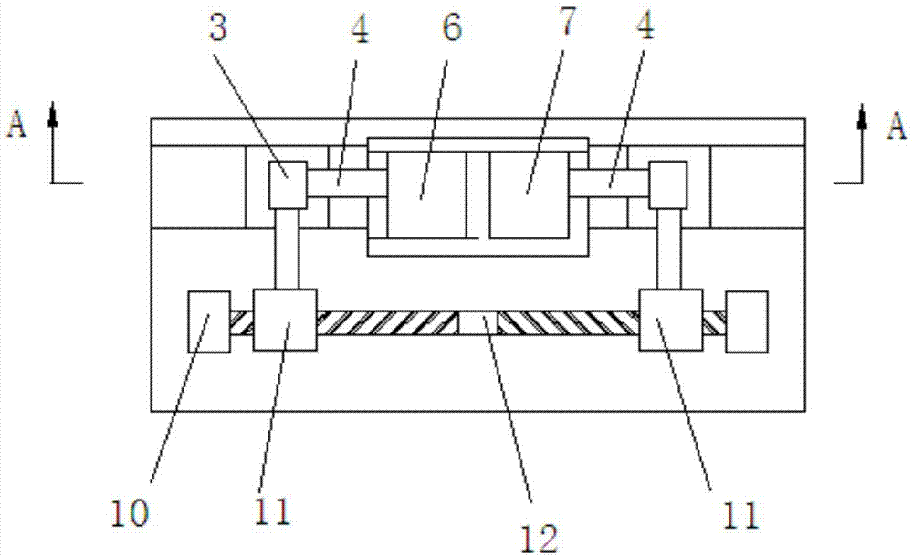
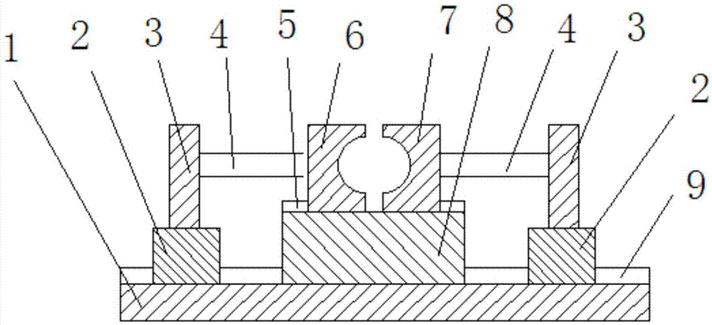
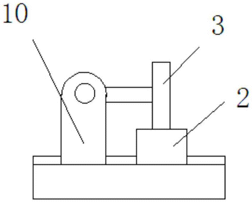
[0022] Such as figure 1 , figure 2 and image 3 As shown, a steel pipe clamping mechanism includes a bottom plate 1 on which a driving mechanism, a clamping mechanism and a pushing mechanism are arranged, and the clamping mechanism includes a base 8, a left clamping block 6 and a right clamping Block 7 is provided with a second chute 5 on the left and right direction on the top surface of the base 8, and the left clamping block 6 and the right clamping block 7 are respectively arranged in the second chute 5, the left clamping The block 6 and the right clamping block 7 are slidably connected through the second chute 5 and the base 8 respectively, and the left clamping block 6 and the ...


PUM


Abstract

The invention provides a steel pipe clamping mechanism which comprises a bottom plate; a driving mechanism, a clamping mechanism and pushing mechanisms are arranged on the bottom plate; the clamping mechanism comprises a base, a left clamping block and a right clamping block; the base is fixedly connected with the bottom plate; the left clamping block and the right clamping block are respectively and movably arranged on the top surface of the base; the pushing mechanisms comprise sliding blocks, pushing plates and pushing rods; the sliding blocks are arranged in a first sliding chute in a sliding manner; the pushing plates are fixedly connected to the top surfaces of the sliding blocks; the pushing rods are arranged horizontally; the left clamping block and the right clamping block are respectively connected with the pushing rods and the pushing plates; the driving mechanism comprises a supporting frame and a bi-directional screw rod; the supporting frame is arranged on the bottom plate; the bi-directional screw rod and the first sliding chute are arranged in parallel; the bi-directional screw rod is rotationally connected onto the supporting frame; a left spiral part and a right spiral part of the bi-directional screw rod are in threaded connection with the connecting blocks respectively; the two connecting blocks and the pushing mechanisms are arranged correspondingly; and each connecting block is fixedly connected with one corresponding pushing plate.

Description

technical field [0001] The invention belongs to the field of steel pipe production, and in particular relates to a steel pipe clamping mechanism. Background technique [0002] In the current steel pipe production, the steel pipe is cut into a certain length according to the needs of customers. In the steel pipe cutting technology, the steel pipe is fixed by a clamping mechanism, and then cut by a cutter. The existing steel pipe fixing device generally includes a fixed The lower clamping block and the movable upper clamping block, during the steel pipe clamping process, place the steel pipe on the lower clamping block, open the pushing element of the upper clamping block, and press down the upper clamping block until the steel pipe is fixed , the clamping mechanism is more complicated and not suitable for modern enterprise production. Contents of the invention [0003] In view of this, the present invention aims to propose a steel pipe clamping mechanism to solve the probl...

Claims


Application Information

Patent Timeline
Patent Type & Authority Applications(China)
IPC IPC(8): B23Q3/06
CPCB23Q3/064
Inventor 崔建国
Owner 天津建通管业有限公司
Why Eureka
Try Eureka