
Truss hinging lug connection structure, truss extending boom, boom system and crane

A technology for connecting structures and trusses, applied in the direction of cranes, etc., can solve the problems of cracking, limiting lifting performance, and high composite stress

Active Publication Date: 2016-03-30
ZOOMLION HEAVY IND CO LTD
View PDF7 Cites 0 Cited by
  • Summary
  • Abstract
  • Description
  • Claims
  • Application Information

AI Technical Summary

Problems solved by technology

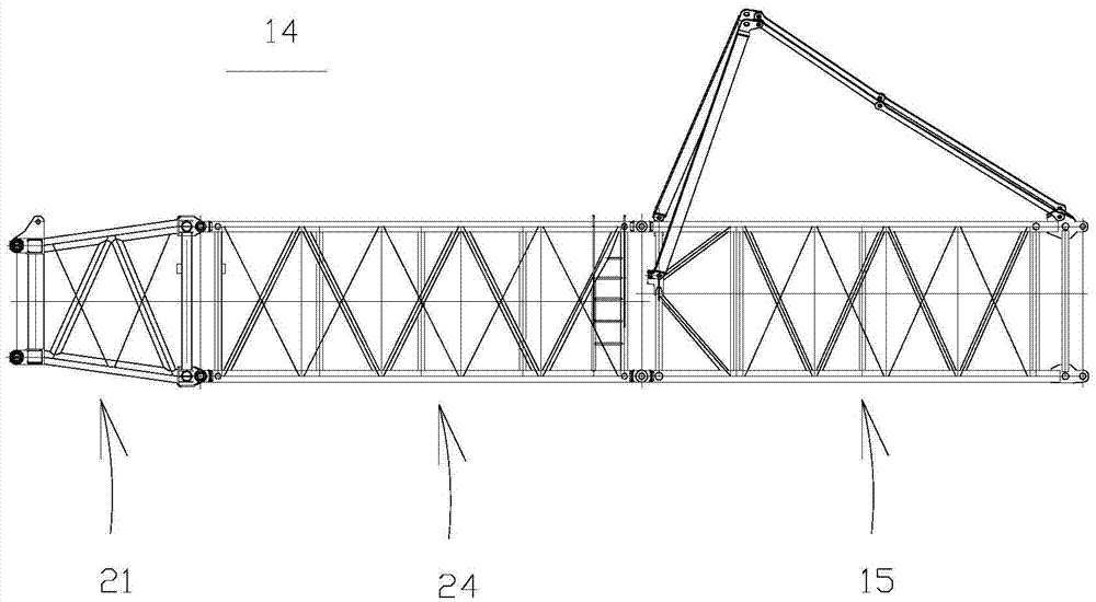
However, this goose-head jib system also has some deficiencies. For example, the truss hinge lugs at the turning point of the goose-head jib truss structure are made of existing general and traditional solid cylindrical steel hinge lugs and are butt welded, that is, the outer diameter One end of the solid cylindrical steel that is approximately equal to the outer diameter of the truss chord is flattened into one or two hinge lugs and the overhead holes are cut, and then the other end of the solid cylindrical steel is cut into a conical shape slightly smaller than the inner diameter of the butt chord and inserted into the butt joint. inside the chord, and then directly weld the solid cylindrical steel and the chord along the circumferential direction
However, during the hoisting operation, the hoisting end at one end of the goose-head truss structure in the prior art lifts heavy objects, and correspondingly the solid cylindrical steel reformed hinge lug at the other end of the goose-head truss structure is at the butt weld between it and the chord. It must be subjected to axial tension and vertical shear force at the same time, and the traditional connection hinge lug is doomed to have a limited butt weld length and no better local strengthening method, so the hinge lug connection weld of this two-way force is easy to be caused by compound stress. High and cracked, this inevitably greatly limits the improvement of the overall lifting performance, making such a crane unable to perform some wind power hoisting operations with higher requirements

Method used


Image

  • Truss hinging lug connection structure, truss extending boom, boom system and crane
  • Truss hinging lug connection structure, truss extending boom, boom system and crane
  • Truss hinging lug connection structure, truss extending boom, boom system and crane

Examples


Embodiment Construction

[0042] Specific embodiments of the present invention will be described in detail below in conjunction with the accompanying drawings. It should be understood that the specific embodiments described here are only used to illustrate and explain the present invention, and are not intended to limit the present invention.

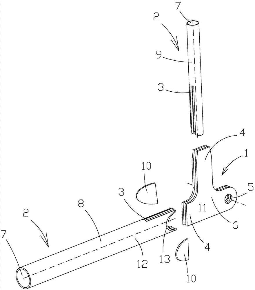
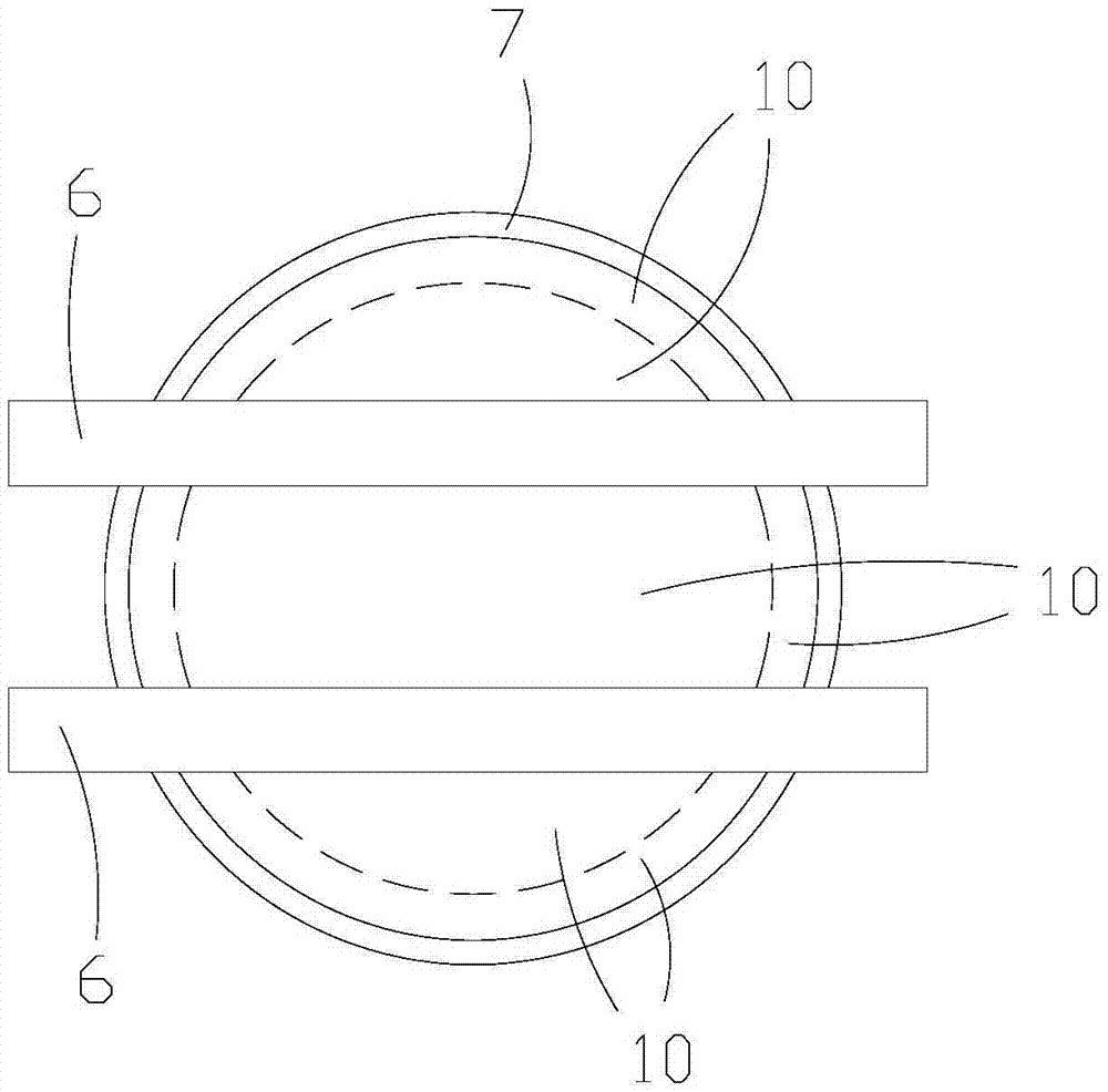
[0043] Such as figure 1 As shown, the hinge lug connection structure of the truss of the present invention includes a hinge lug 1 and a connecting rod 2 fixedly connected, wherein a radially penetrating notch 3 is formed on the end surface of one of the hinge lug 1 and the connecting rod 2, The notch 3 extends axially for a set distance from the end face, and a protruding part 4 is formed on the other, for example, a notch 3 is formed on the connecting rod 2, and a protruding part 4 is formed on the hinge ear piece 1, The protruding portion 4 is axially embedded in the notch 3 , so that an axially extending fixed contact band is formed between the protruding po...


PUM


Abstract

The invention relates to the field of booms, and discloses a truss hinging lug connection structure, a truss extending boom, a boom system and a crane. The truss hinging lug connection structure comprises a hinging lug part (1) and connecting rods (2) fixedly connected with the hinging lug part (1), wherein radially-penetrating notches (3) are formed in one of the end face of the hinging lug part (1) and the end face of each connecting rod (2), and the notches (3) extend from the end faces in the axial direction by a set distance; extending portions (4) are formed on the other of the end face of the hinging lug part (1) and the end face of each connecting rod (2), the extending portions (4) are embedded into the notches (3) in the axial direction to enable axial-extending fixed contact zones to be formed between the extending portions (4) and the notches (3), and therefore the connecting strength of the hinging lug can be effectively improved, and the manufacturing cost of the hinging lug can be relatively lowered.

Description

technical field [0001] The invention relates to the technical field of crane jibs, in particular to a truss hinge lug connection structure, a truss extension jib, a jib system and a crane. Background technique [0002] At present, the boom is an essential working part of construction cranes. When carrying out wind power hoisting operations, there are certain defects in the combination mode of the traditional main telescopic jib or the standard fixed jib of the crane, that is, either the height or the width is not enough, or when the height and width of the arm head are sufficient, the lifting of heavy objects will be due to The jib frame is too close to cause "touch bar" interference, which leads to a sufficient height of the boom head, but the lifting height of the heavy object is not enough, which makes it difficult to install and dismantle the wind power plant. [0003] In order to overcome the above defects and meet the higher and heavier wind power hoisting requirement...

Claims


Application Information

Patent Timeline
Patent Type & Authority Applications(China)
IPC IPC(8): B66C23/64B66C23/70
CPCB66C23/64B66C23/701
Inventor 钟清平蒋冬冬
Owner ZOOMLION HEAVY IND CO LTD
Learn More