Curtain rolling travel control structure

A stroke control and curtain technology, applied in the direction of windows/doors, building components, building structures, etc., can solve the problems of gap friction, small volume of ball 90, increase manufacturing cost, etc., to reduce the difficulty of structural assembly and reduce the obvious step difference , the effect of reducing manufacturing costs

Inactive Publication Date: 2016-03-30
FULL SHUAY ENTERPRISE
View PDF4 Cites 4 Cited by
  • Summary
  • Abstract
  • Description
  • Claims
  • Application Information

AI Technical Summary

Problems solved by technology

[0003] It is not difficult to find the disadvantages of the above-mentioned known structure in detail, the main reasons are as follows: (1), the stroke control structure of the known curtain is mainly through the ball matching the groove of the rotating shaft, and the guide groove 61 with the shaft sleeve 60 Positioning, so that when the rotating shaft 70 and the curtain form a synchronous rotating state, the ball 90 can be linked to reach the locking or disengaging state, but the volume of the ball 90 is small, and it needs to be assembled in a more precise manner, and the groove of the rotating shaft 70 The groove 71 and the guide groove 61 of the shaft sleeve 60 must also be carefully designed so that the ball 90 can be accurately positioned or disengaged from sliding, which will cause inconvenience in structural manufacturing and assembly, thereby increasing the manufacturing cost and not having economic benefits. The ball 90 is also easy to miss and get lost during the assembly process, forming a defective product. In addition, when sliding and shifting between the rotating shaft 70 and the sleeve 60, there will also be a gap friction problem, which will cause the curtain puller to operate unsmoothly, which is not practical. sex
[0004] (2), moreover, the positioning of the groove 71 of the known rotating shaft 70 and the guide groove 61 of the matching shaft sleeve 60 has a regularity in the cycle, so that the positioning effect of the curtain must be achieved by rotating the rotating shaft 70 once. In the stuck state, the positioning accuracy of the curtain is not good, and when the pull is positioned, it is easy to roll back and cause a height difference. It does not have the stability of curtain opening and closing, and lacks the effect of accurate positioning of the curtain.

Method used


Image

  • Curtain rolling travel control structure
  • Curtain rolling travel control structure
  • Curtain rolling travel control structure

Examples


Embodiment Construction

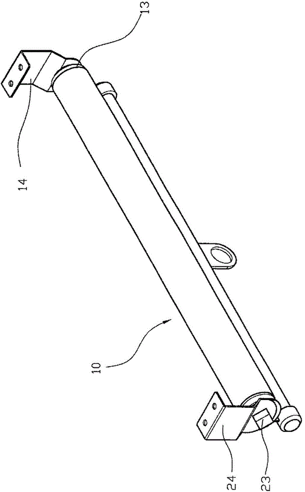
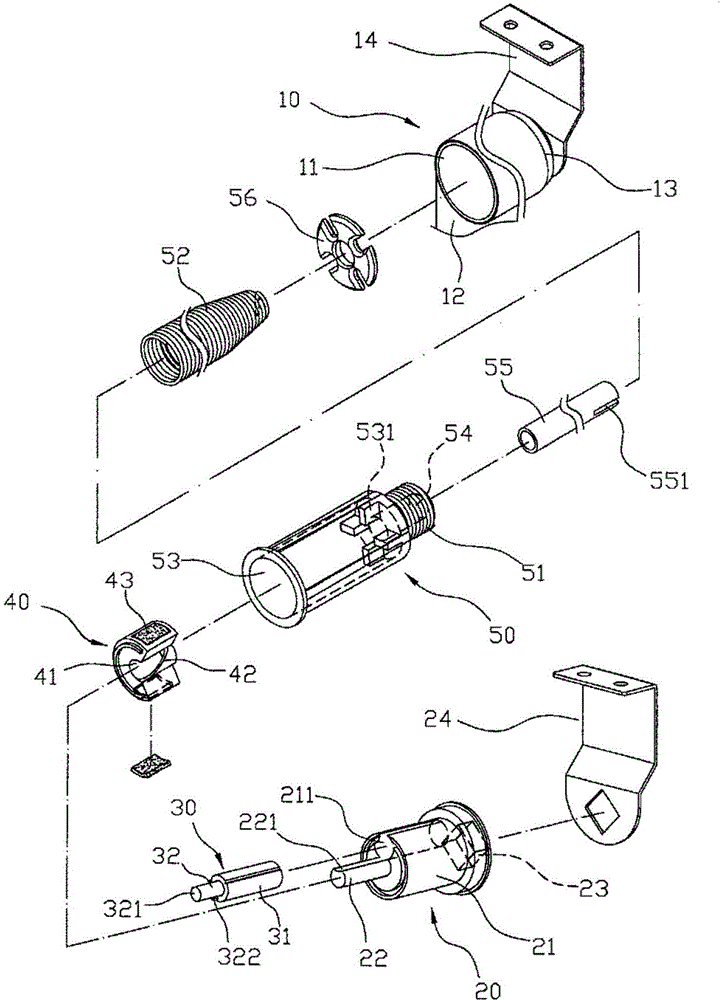
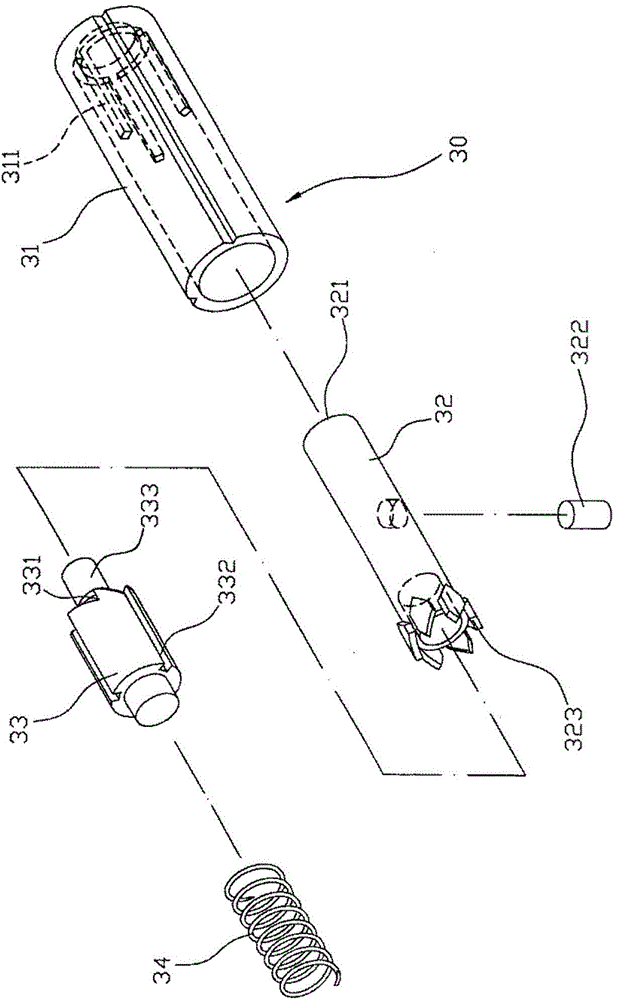
[0036] First, please see figure 1 , 2 Cooperate image 3 , 4As shown, a curtain retracting stroke control structure, which includes: a curtain body 10, an assembly 20, a catch 30, a toggle unit 40 and a shaft sleeve 50, a curtain body 10 has a Shaft tube 11, and the curtain piece 12 is rolled by the shaft tube 11, and a combination part 20 has a combination part 21, and the center of the combination part 21 extends a combined convex column 22, and is assembled eccentrically on one side of the combined convex column 22. There is a catch 30, wherein the combination part 21 of the assembly 20 is in the shape of a cylinder, and the combination part 21 is eccentrically provided with a combination container 211 to provide the assembly of the catch 30, and the combination boss 22 faces the combination container. The end surface of the groove 211 forms a dodging arc surface 221, and the outer end of the assembly 20 has a non-cylindrical combined convex portion 23, which is embedde...


PUM


Abstract

The invention provides a curtain rolling travel control structure comprising a curtain body, an assembly member, a detent member, a stirring unit and a rotary shaft sleeve. Through the detent member of an elastic pressing switch, the curtain is located. Through the movement of protruding and inwards-retracting of the pressed detent member, clamping and inlaying position or disengaging is formed between the detent member and positioning ribs. Through the control structure, the usage of the curtain body is more accurate and convenient; and the difficulty of structure assembly is reduced; the manufacture and assembly of the structure are simpler; the manufacture cost is effectively reduced; the production efficiency is greatly increased and the control structure has economic benefit. Furthermore, multiple positioning ribs and multiple clamping and inlaying position states are provided between the rotary shaft sleeve and the detent member so that the accuracy of positioning is effectively increased, obvious segment difference caused by the curtain rolling travel is reduced, and the stability of curtain unfolding and folding is increased.

Description

technical field [0001] The invention relates to a curtain structure, in particular to a curtain retraction stroke control structure. Background technique [0002] A travel actuator for curtains is known, please cooperate and participate Figure 18 , 19 As shown, it is provided with a shaft sleeve 60, and the inner wall of the hollow part of the shaft sleeve 60 is provided with a guide groove 61 in the axial direction, and a rotating shaft 70 and a rolling rod assembly 80 are arranged in the hollow part of the shaft sleeve 61, and the A groove 71 is provided on the surrounding wall of the rotating shaft 70, and a locking recess 711 is formed at the proper position of the groove 71, and a ball 90 is provided between the groove 71 of the rotating shaft 70 and the guide groove 91 of the shaft sleeve 60, and a ball 90 is provided on the rolling rod. A spring 81 is assembled between the vertical part 80 and the rotating shaft 70, and one end of the spring 81 is fixedly connected ...

Claims


Application Information

Patent Timeline
IPC IPC(8): E06B9/80E06B9/42
Inventor 董正宗
Owner FULL SHUAY ENTERPRISE
Why Eureka
Try Eureka