Optical lens, camera module and electronic equipment
An optical lens and lens technology, applied in optics, optical components, instruments, etc., can solve the problems of optical lens production, increased manufacturing difficulty, high optical lens manufacturing cost, and increased assembly difficulty, so as to control manufacturing cost and reduce structural assembly Difficulty and improvement of assembly yield
- Summary
- Abstract
- Description
- Claims
- Application Information
AI Technical Summary
Problems solved by technology
Method used
Image

Examples
Embodiment 1
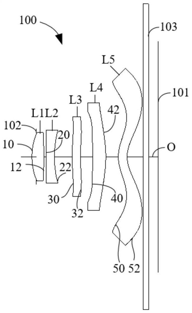
[0088] The schematic structural diagram of the optical lens 100 disclosed in the first embodiment of the present application is as follows: figure 1 As shown, the optical lens 100 includes a diaphragm 102, a first lens L1, a second lens L2, a third lens L3, a fourth lens L4, a fifth lens L5, an infrared lens, and a diaphragm 102, which are sequentially arranged along the optical axis O from the object side to the image side. Filter 103 and imaging surface 101.
[0089] Among them, the optical power distribution of the above five-piece lens is shown in Table 1 below:
[0090] Table 1
[0091] Lens code L1 L2 L3 L4 L5 Power distribution just burden just just burden
[0092] Further, the object side 10 and the image side 12 of the first lens L1 are convex surfaces at the near optical axis, the object side 20 of the second lens L2 is convex at the near optical axis, and the image side 22 of the second lens L2 is near the optical axis. The optic...
Embodiment 2
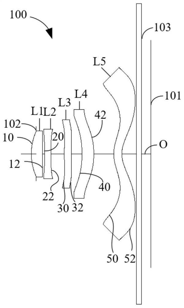
[0109] Please refer to image 3 , image 3 It is a schematic structural diagram of the optical lens 100 according to the second embodiment of the present application. The optical lens 100 includes a diaphragm 102 , a first lens L1 , a second lens L2 , a third lens L3 , a fourth lens L4 , a fifth lens L5 , and an infrared filter, which are sequentially arranged along the optical axis O from the object side to the image side. 103 and the imaging plane 101.
[0110] Among them, the optical power distribution of the above five-piece lens is shown in Table 4 below:
[0111] Table 4
[0112]
[0113]
[0114] Further, the object side 10 and the image side 12 of the first lens L1 are convex surfaces at the near optical axis, the object side 20 of the second lens L2 is concave at the near optical axis, and the image side 22 of the second lens L2 is near the optical axis. The optical axis is concave. The object side 30 of the third lens L3 is convex at the near optical axis,...
Embodiment 3
[0125] Please refer to Figure 5 , Figure 5 A schematic structural diagram of the optical lens 100 according to the third embodiment of the present application is shown. The optical lens 100 includes a diaphragm 102 , a first lens L1 , a second lens L2 , a third lens L3 , a fourth lens L4 , a fifth lens L5 , and an infrared filter, which are sequentially arranged along the optical axis O from the object side to the image side. 103 and the imaging plane 101.
[0126] Among them, the optical power distribution of the above-mentioned five-piece lens is shown in Table 7 below:
[0127] Table 7
[0128] Lens code L1 L2 L3 L4 L5 Power distribution just burden burden just burden
[0129] Further, the object side 10 and the image side 12 of the first lens L1 are convex surfaces at the near optical axis, the object side 20 of the second lens L2 is concave at the near optical axis, and the image side 22 of the second lens L2 is near the optical axi...
PUM
 Abstract
Description
Claims
Application Information