Rotary air-compressing load switch and nozzle assembly thereof
A technology of load switch and rotary compression, which is applied in the fields of spout assembly and rotary compressor load switch, which can solve the problems of reduced reliability of the switch, increased operation impact, and waste of mechanism operation work, so as to improve the breaking performance and reduce the operation impact , Reduce the effect of operating work
- Summary
- Abstract
- Description
- Claims
- Application Information
AI Technical Summary
Problems solved by technology
Method used
Image
Examples
no. 1 example
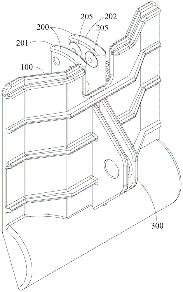
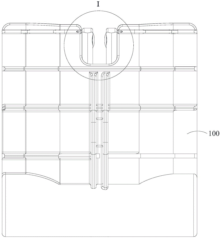
[0035] Such as Figure 5 As shown, in the rotary compressed air load switch of the first embodiment of the present invention, the rotary piston 100 of the arc extinguishing chamber is fitted on the moving contact knife (or called the moving contact) 200, and the moving contact knife 200 is installed on the lower static contact 22, The rotary piston 100 is equipped with a cylinder 27 . When the rotary pneumatic load switch of the embodiment of the present invention is opened, that is, the combination of the rotary piston 100 and the movable contact blade 200 is in the cylinder 27, away from the upper static contact 21 from the position connected to the upper static contact. When the direction of the head 21 is rotated, the rotary piston 100 compresses the gas in the cylinder 27 .
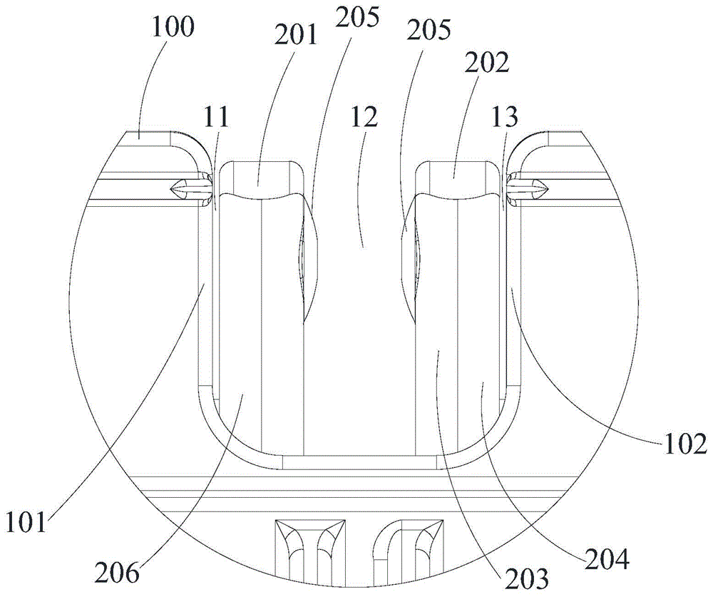
[0036] In the nozzle assembly of the first embodiment of the present invention, the technical solution adopted is that the air outlet 10 of the nozzle assembly is arranged on the rotary piston 100 o...
no. 2 example
[0046] The parts of this embodiment that are the same as those of the first embodiment will not be repeated here.
[0047] Such as Figure 6-Figure 8 As shown, the difference between this embodiment and the first embodiment is that in this embodiment, only the main nozzle 12 and the first side nozzle 11 are provided, instead of the second side nozzle. Correspondingly, the air outlet 10 has the first One side 101 and the second side 104, the difference between the second side 104 of this embodiment and the second side 102 in the first embodiment is that the second side 104 is no longer vertically arranged, and It has a certain inclination. In this embodiment, the gas passes through the main nozzle 12 and the first side nozzle 11 to extinguish the arc, so an arc striking device can be installed on the first blade 201 to guide the arc to the side of the first blade 201 .
[0048] In addition, the left side view of the spout assembly of other embodiments can be compared with F...
no. 3 example
[0050] The parts of this embodiment that are the same as those of the first embodiment will not be repeated here.
[0051] Such as Figure 9 with Figure 10 As shown, the difference between this embodiment and the first embodiment is that in this embodiment, only the main nozzle 12 and the second side nozzle 13 are provided, instead of the first side nozzle. Correspondingly, the air outlet 10 has the second side nozzle One side 109 and the second side 102, the difference between the first side 109 of this embodiment and the first side 101 in the first embodiment is that the first side 101 is no longer vertically arranged, and It has a certain inclination. In this embodiment, the gas passes through the main nozzle 12 and the second side nozzle 13 to extinguish the arc, so an arc striking device can be provided on the second blade 202 to lead the arc to the side of the second blade 202 .
PUM
 Abstract
Description
Claims
Application Information
 - R&D
- Intellectual Property
- Life Sciences
- Materials
- Tech Scout
- Unparalleled Data Quality
- Higher Quality Content
- 60% Fewer Hallucinations
Browse by: Latest US Patents, China's latest patents, Technical Efficacy Thesaurus, Application Domain, Technology Topic, Popular Technical Reports.
© 2025 PatSnap. All rights reserved.Legal|Privacy policy|Modern Slavery Act Transparency Statement|Sitemap|About US| Contact US: help@patsnap.com


