

Uplink transmission method, base station and terminal
A transmission method and terminal technology, applied in electrical components, wireless communication, etc., can solve problems such as difficulty in using LTE technology, lack of back-off mechanism, and interference
- Summary
- Abstract
- Description
- Claims
- Application Information
AI Technical Summary
Problems solved by technology
Method used
Image

Examples
Embodiment 1
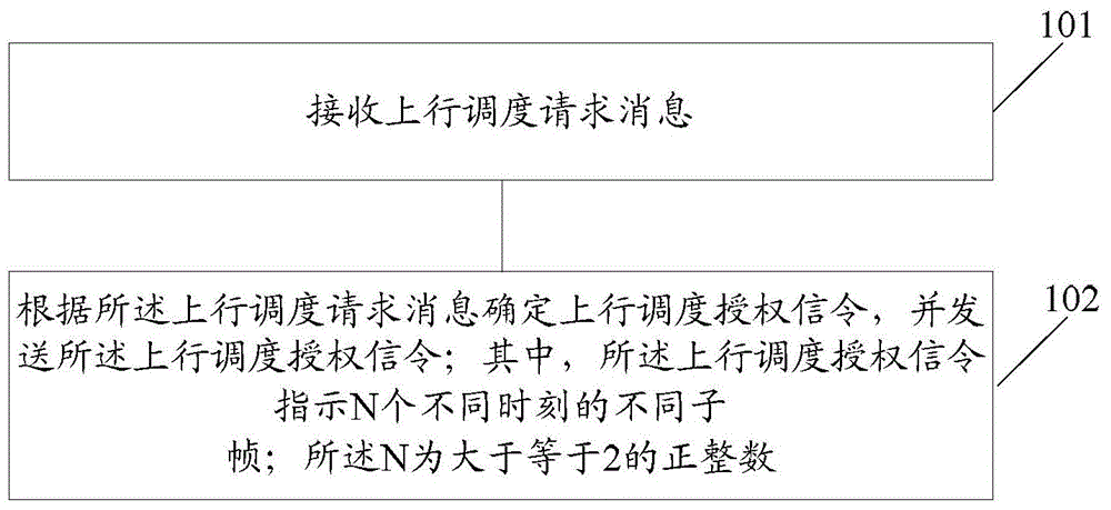
[0106] figure 1 It is a schematic diagram of the implementation process of the uplink transmission method in the embodiment of the present invention Figure 1 ;Such as figure 1 As shown, the method is applied to the base station side; the method includes:
[0107] Step 101: receiving an uplink scheduling request message;
[0108] Step 102: Determine the uplink scheduling grant signaling according to the uplink scheduling request message, and send the uplink scheduling grant signaling; wherein, the uplink scheduling grant signaling indicates N different subframes at different times; the N is A positive integer greater than or equal to 2.
[0109] Here, the N different subframes at different times indicated in the uplink scheduling grant signaling correspond to channels corresponding to unlicensed spectrum in the LTE system.
[0110]Here, the uplink scheduling grant signaling itself may identify whether its corresponding frequency band is a frequency band on the licensed spe...
Embodiment 2
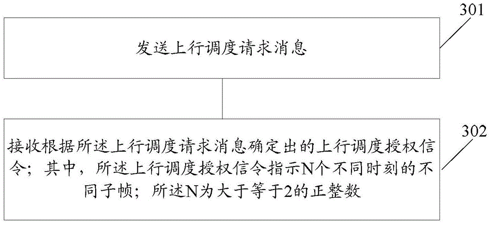
[0129] image 3 It is a schematic diagram of the implementation process of the uplink transmission method in the embodiment of the present invention Figure II ;Such as image 3 As shown, the method is applied to the terminal side; the method includes:
[0130] Step 301: sending an uplink scheduling request message;
[0131] Step 302: Receive the uplink scheduling grant signaling determined according to the uplink scheduling request message; wherein, the uplink scheduling grant signaling indicates N different subframes at different times; the N is a positive integer greater than or equal to 2.
[0132] In the above solution, the N different subframes at different times indicated in the uplink scheduling grant signaling correspond to channels corresponding to unlicensed spectrum in the long term evolution system.
[0133] Here, the terminal sends an uplink scheduling request message to the base station, and the base station receives the uplink scheduling request message, det...
Embodiment 3
[0203] After receiving the uplink scheduling authorization signaling sent by the base station, the terminal performs uplink channel detection according to the uplink scheduling opportunity indicated by the uplink scheduling authorization signaling to lay the foundation for sending uplink service data; wherein, the uplink scheduling opportunity includes N , that is, N different subframes at different times; said N is a positive integer greater than or equal to 2; after N times of detection, the terminal finds that the interference in the channel to be transmitted is relatively large or the background noise is high, that is, it is considered that N times of uplink scheduling If the channels of the opportunity are all busy and cannot perform data transmission, the terminal will give up this uplink scheduling request after the N detection.
[0204] Figure 5 It is a schematic flow diagram of the specific implementation of the uplink transmission method in the embodiment of the pre...
PUM
 Abstract
Description
Claims
Application Information