Supercharge Your Innovation With Domain-Expert AI Agents!

Pump for pumping a liquid

A technology for conveying liquids and liquids, which is applied in the field of exhaust pipeline devices

Active Publication Date: 2016-03-30
VTESCO TECH GMBH
View PDF7 Cites 3 Cited by
  • Summary
  • Abstract
  • Description
  • Claims
  • Application Information

AI Technical Summary

Problems solved by technology

Furthermore, during delivery, there should be as little pressure fluctuations as possible in the liquid additive, since these pressure fluctuations would adversely affect the spray pattern of the nozzles for atomizing the liquid additive in the exhaust gas treatment system

Method used


Image

  • Pump for pumping a liquid
  • Pump for pumping a liquid
  • Pump for pumping a liquid

Examples


Embodiment Construction

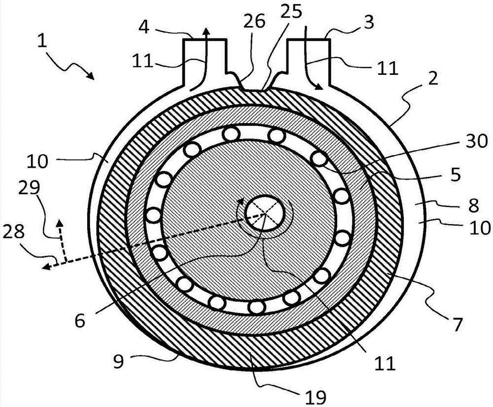
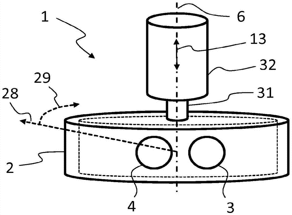
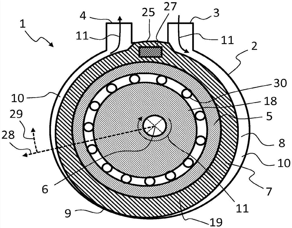
[0064] figure 1 with image 3 Two different specific embodiments of the pump 1 are shown, each having a deformable membrane 19 as deformable element 7 . To illustrate the pump, the figure 1 with 3 A coordinate system with axis 6 , radial direction 28 and circumferential direction 29 is shown in .

[0065] The deformable element 7 is arranged in the pump housing 2 between the pump housing 2 and the eccentric 5 . The pump housing 2 has an inlet 3 through which liquid can flow into the pump housing 2 in a conveying direction 11 , and an outlet 4 through which liquid can flow out of the pump housing 2 in a conveying direction 11 . The eccentric 5 is arranged rotatably about an axis 6 in the pump housing 2 . When the eccentric 5 rotates, the rotation of the eccentric 5 is converted via the bearing 30 into a rolling motion of the deformable element 7 on the pump housing 2 . As a result, the deformable element 7 locally abuts against the pump housing 2 and forms a seal 9 . Bet...


PUM


Abstract

The invention relates to a pump (1) for pumping a liquid, having a pump housing (2) with at least one inlet (3) and at least one outlet (4). The pump housing (2) is equipped with an eccentric (5) which can be rotated relative to the pump housing (2) by an axle (6). A deformable element (7) is arranged between the pump housing (2) and the eccentric (5), and by means of the deformable element (7), at least one pump path (8) from the at least one inlet (3) to the at least one outlet (4) is delimited and at least one movable pump path (8) seal (9) is formed which separates at least one closed pump volume (10) in the pump path (8). The at least one movable seal (9) can be moved in a pump direction (11) from the inlet (3) to the outlet (4) by a movement of the eccentric (5) in order to pump the fluid along the pump path (8). Furthermore, the pump (1) has at least one adjustable axial calibrating device (12), by means of which the deformable element (7) is clamped in the axial direction (13) parallel to the axle (6).

Description

technical field [0001] The invention relates to a pump for conveying liquids, which is particularly suitable for conveying liquid additives into the exhaust gas line arrangement of an internal combustion engine. Background technique [0002] Exhaust gas treatment devices are known for purifying the exhaust gas of an internal combustion engine, to which a liquid additive is fed for purifying the exhaust gas. The exhaust gas purification method carried out in such an exhaust gas treatment device is a selective catalytic reduction method (SCR method; SCR=selective catalytic reduction), in which nitrogen oxides in the exhaust gas are reduced by means of a reducing agent. In particular ammonia is used as reducing agent. Ammonia is generally not stored directly in motor vehicles, but is present in the form of a liquid additive in the form of a reducing agent precursor solution. The liquid additive can be converted into the reducing agent inside the exhaust gas (in the exhaust ga...

Claims


Application Information

Patent Timeline
Patent Type & Authority Applications(China)
IPC IPC(8): F04B43/12F01N3/20F04B43/14F04C5/00F04B43/00
CPCF01N3/2066F04B43/0054F04B43/12F04B43/123F04B43/14F04C5/00F01N2610/1433F01N2610/02F01N2610/144F04C15/0015F04C15/0065Y02A50/20Y02T10/12F01N3/206F04B43/0081
Inventor J·霍格森R·布吕科
Owner VTESCO TECH GMBH
Features
  • R&D
  • Intellectual Property
  • Life Sciences
  • Materials
  • Tech Scout
  • Unparalleled Data Quality
  • Higher Quality Content
  • 60% Fewer Hallucinations
Learn More