
Mould pressing corrugated type flexible flame isolation device

An isolation device, corrugated technology, applied in the direction of rocket engine device, jet propulsion device, machine/engine, etc., can solve the problems of after-effect reverse roll, destructive effect, etc., achieve good comprehensive performance, and meet the needs of use.

Active Publication Date: 2016-04-06
BEIJING INST OF ASTRONAUTICAL SYST ENG +1
View PDF6 Cites 6 Cited by
  • Summary
  • Abstract
  • Description
  • Claims
  • Application Information

AI Technical Summary

Problems solved by technology

[0005] The purpose of the present invention is to solve the problem that the tail compartment of a heat-launching rocket is easily affected by the destructive effects of the engine flame after-effect rollback and long-term heat radiation during take-off. It has the functions of flame backwashing and flexible nozzle swing compensation, and also has a molded corrugated flexible flame isolation device with small size, light weight, high strength, simple operation, and good high and low temperature performance.

Method used


Image

  • Mould pressing corrugated type flexible flame isolation device
  • Mould pressing corrugated type flexible flame isolation device
  • Mould pressing corrugated type flexible flame isolation device

Examples


Embodiment Construction

[0019] The present invention will be further described below in conjunction with the accompanying drawings and embodiments.

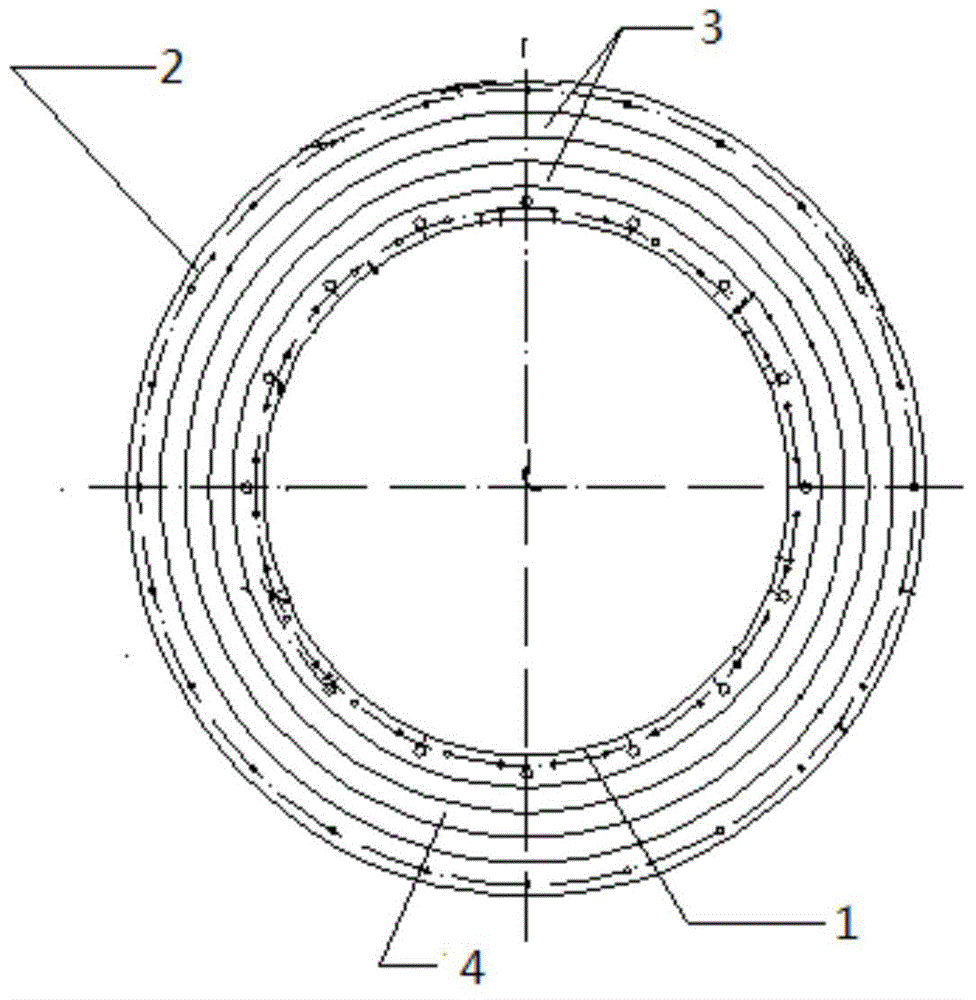
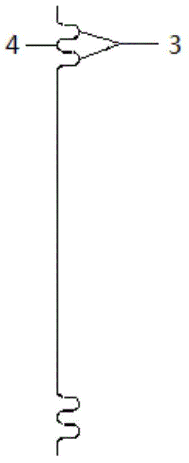
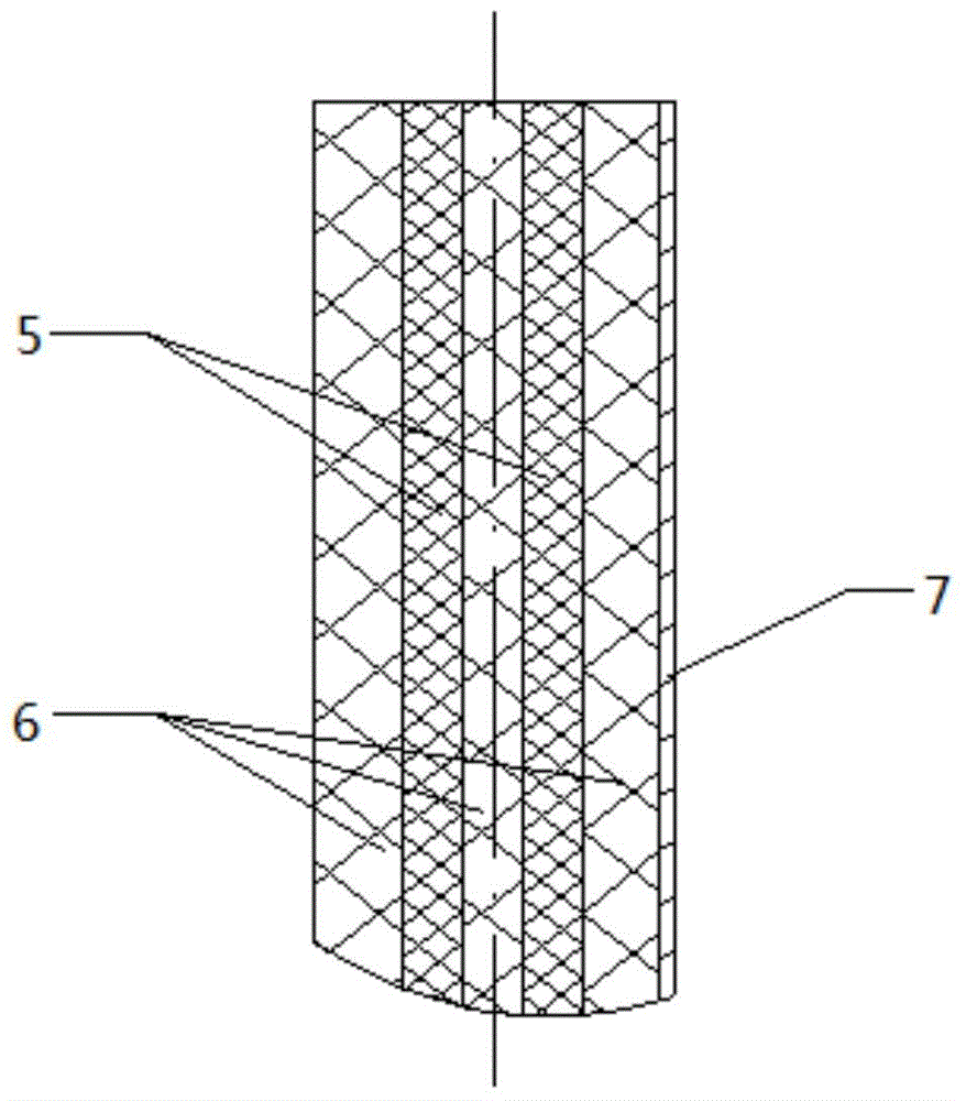
[0020] Such as figure 1 As shown, a molded corrugated flexible flame isolation device has a ring-shaped structure as a whole, and an inner trimming edge 1, an outer trimming edge 2 and a corrugated structure are arranged on the annular structure. The inner trimming edge 1 is located at the innermost side of the annular structure, and the inner trimming edge 1 is fixedly connected with the nozzle flange of the rocket engine. The corrugated structure is located outside the inner trimming edge 1 . The outer trimming edge 2 is located outside the corrugated structure, and the outer trimming edge 2 is fixedly connected with the lower end surface of the rocket tail cabin. The inner trim 1 is used to closely fit the rocket engine, the outer trim 2 is used to closely fit the rocket tail compartment, and the corrugated structure is used to provide space for th...


PUM


Abstract

The invention relates to the technical field of heat protection and insulation, in particular to a mould pressing corrugated type flexible flame isolation device. The device aims to solve the problem that a heat emission rocket stern room is prone to the frustrating effect of engine flame take-off aftereffect back scrolling and long-term heat radiation. The mould pressing corrugated type flexible flame isolation device is characterized in that the whole mould pressing corrugated type flexible flame isolation device is of a ring type structure, and an inner shearing edge, an outer shearing edge and a corrugated structure are arranged on the ring type structure; the inner shearing edge is located on the innermost side of the ring type structure and is fixedly connected with a spraying pipe flange of the rocket stern room; the corrugated structure is located on the outer side of the inner shearing edge; the outer shearing edge is located on the outer side of the corrugated structure and fixedly connected with the lower end face of the rocket stern room; the inner shearing edge is used for being tightly attached to a rocket engine, the outer shearing edge is used for being tightly attached to the rocket stern room, and the corrugated structure is used for providing space for swinging of the rocket engine. Flexible compensation for a swinging engine spraying pipe is finished, the whole radiant heat prevention and flame reflux ablation prevention functions are also achieved, and the good comprehensive performance is achieved.

Description

technical field [0001] The invention relates to the technical field of heat-insulating structures, in particular to a molded corrugated flexible flame isolation device. Background technique [0002] At present, there are two ways to take off and launch large-scale rockets, missiles and other aircraft, one is cold launch and the other is hot launch. Both methods have their own advantages. According to different environments and requirements, both have been widely used in actual combat. Among them, the thermal launch method has been widely adopted by the military and satellite launch users due to its short launch preparation time, simple operation, no need for cumbersome ground equipment support, and significant economy. [0003] The main feature of thermal launch is that rockets and missiles are erected on the launch pad and ignited directly for take-off. The main problem that needs to be solved is that the engine flame is rewinded after being diverted through the diversion ...

Claims


Application Information

Patent Timeline
Patent Type & Authority Applications(China)
IPC IPC(8): F02K9/00F02K9/97
Inventor 杨若丽朱广生张凤立陈红波高波陈瑛张延瑞高雅靳佳波陈志会顾胜宁雷郑浩廖锡广葛欣闫海建傅丹
Owner BEIJING INST OF ASTRONAUTICAL SYST ENG
Learn More